


33
CONTROLS AND SWITCHES
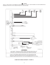
This model is provided with three pressure switches. These switches
are essential to the safe and proper operation of the unit. All switches
are wired in series. The controller is set up to shut the unit down
whenever there is a failure of any of the switches. It is important to
understand the purpose of each switch.
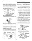
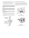
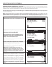
FIGURE 33.
BLOWER PROVER SWITCH
(SEE FIGURE 33)
The Blower Prover Switch is provided on the heater to verify that
the fan is operating. It is a positive pressure switch whose electrical
contacts are normally open. When the fan increases the pressure
in the burner, the pressure switch will allow the electrical contacts
to close. The pressure switch is connected to the burner tap by a
piece of tygon tubing. This tubing must be connected in order for
the switch to change the electrical contacts. The controller requires
that the electrical contacts on this air ow switch be open before it
will allow the blower to come on.
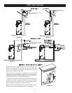
BLOCKED EXHAUST SWITCH
(SEE FIGURE 33)
The Blocked Exhaust Switch is set up to shut the unit off when a
build-up of positive pressure in the exhaust vent pipe occurs. This
switch is a positive pressure switch that requires an increase in
pressure to change the electrical contacts from normally closed to
open. When this switch prevents the unit from igniting, most likely the
exhaust is blocked by some means. Check to see if the condensate
is allowed to ow freely from the exhaust elbow and for obstructions
in the exhaust venting and exhaust vent terminal. Also verify that
the vent length does not exceed the maximum allowed as shown in
the Vent Section of this manual.
BLOCKED INTAKE SWITCH
(SEE FIGURE 33)
The Blocked Intake Switch is set up to shut the unit off when
a build-up of negative pressure in the intake air pipe occurs.
This switch is a negative pressure switch that requires an
increase in negative pressure to change the electrical contacts
from normally closed to open. The switch is connected to the
pressure tap on the PVC pipe connected to the inlet of the
blower. When this switch prevents the unit from igniting, most
likely the intake is blocked. Verify that the screen on the intake
air connection (conventional vent), the intake air pipe and
termination (direct vent installations) are free of obstructions
that may prevent air from entering the unit. Insure the screen
on intake air connection has been removed on direct vent
installations, see Figure 15. Also verify the intake air pipe length
does not exceed the maximum allowed as shown in the Venting
Section (See Table 5) of this manual.
ON/OFF SWITCH
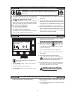
The ON/OFF Switch is a single-pole, single-throw rocker switch. This
switch provides 120V from the line source to the heater.
CAUTION
THE WATER HEATER IS POLARITY SENSITIVE. BEFORE
APPLYING ELECTRICITY TO THIS HEATER BE CERTAIN THAT
SUPPLY NEUTRAL WIRE TO GROUND CHECK INDICATES
ZERO VOLTAGE.
HOT SURFACE IGNITER
The Hot Surface Igniter is a device that ignites the main burner by
high temperature (>1800°F or >982°C). When 120VAC is applied
to the igniter, sufcient heat is generated to ignite the main burner.