


27
CONCENTRIC VENT INSTALLATION
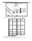
This appliance is certied for concentric venting with concentric
vent kit #9006328005. Follow instructions below for proper
installations.
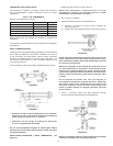
Table 6 - KIT COMPONENTS
Each kit is comprised of the following:
Item Description Qty.
Rain Cap 3 in. 1
SDR-26 pipe 4 in. dia. 1
SDR-26 pipe 2½ in. dia. 1
Y Concentric Fitting 3 in. 1
Installation Instructions 194504 1
Field supplied pipe and ttings are required to complete the
installation.
This concentric vent termination kit may be used with 3 inch diameter
pipe systems.
SAFETY CONSIDERATIONS
Installing and servicing water heating equipment can be hazardous
due to gas and electrical components. Installation and service
of the concentric vent termination requires ability equivalent
to that of a qualied installer or service agent, see page 7. All
precautions in the literature, on tags, and labels attached to the
unit must be observed.
Follow all safety codes. Wear safety glasses and work gloves.
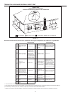
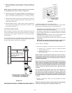
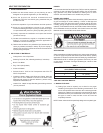
FIGURE 20.
FIGURE 21.
* Dimension 21 1/8 in. may be lengthened to 60 in. maximum.
Dimension 21 1/8 in. may also be shortened by cutting the
pipes, provided in the kit, to 12 in. minimum.
** Dimension 39 will change accordingly as dimension
21 1/8 in. is lengthened or shortened.
Do not use eld-supplied couplings to extend pipes. Airow
restriction will occur and the heater pressure switch may cause
intermittent operation.
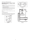
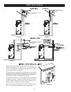
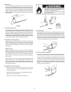
INSTALLATION PROCEDURE 1 ROOF TERMINATION, see
Figure 23.
1. Determine best location for termination kit.
NOTE: Roof termination is preferred since it is less
susceptible to damage, has reduced chances to intake
contaminants, and less visible vent vapors.
2. Cut 1 hole (5 in. diameter)
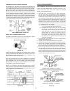
3. Partially assemble concentric vent termination kit.
a) Cement Y concentric fitting to larger diameter kit
pipe, see Figure 20.
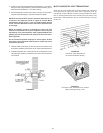
b) Cement rain cap to smaller diameter kit pipe, see Figure 22.
FIGURE 22.
NOTE: Instead of cementing the smaller pipe to the rain cap,
a field-supplied stainless steel screw may be used to secure
the 2 components together when field disassembly is desired
for cleaning, see Figure 22.
When using alternate screw method, drill clearance hole in
rain cap and pilot hole in vent pipe for screw size being used.
Failure to drill adequate holes may cause cracking of PVC
components, allowing combustion products to be recirculated.
Failure to follow this warning could result in personal injury
or death.
Do not operate the heater with rain cap removed or
recirculation of combustion products may occur. Water may
also collect inside larger combustion-air pipe and flow to
the burner enclosure. Failure to follow this warning could
result in product damage or improper operation, personal
injury or death.
4. Install Y concentric fitting and pipe assembly through
structure’s hole and eld supplied roof boot/ashing.
FIGURE 23.
NOTE: Do not allow insulation or other materials to accumulate
inside pipe assembly when installing through hole.