


18
GAS PIPING
Make sure gas supplied is same type listed on model rating plate.
The inlet gas pressure must not exceed 14 inch water column (3.5
kPa) for natural and propane gas (L.P.). The minimum inlet gas
pressure shown on rating plate is that which will permit ring at
rated input.
SEDIMENT TRAPS
A sediment trap shall be installed as close to the gas inlet of the
water heater as practical at the time of water heater installation.
The sediment trap shall be either a tee tting with a capped nipple
in the bottom outlet or other device recognized as an effective
sediment trap.
Contaminants in the gas lines may cause improper operation
of the gas control valve that may result in fire or explosion.
Before attaching the gas line be sure that all gas pipe is clean
on the inside. To trap any dirt or foreign material in the gas
supply line, a drip leg (sometimes called a sediment trap) must
be incorporated in the piping. The drip leg must be readily
accessible. Install in accordance with the “Gas Piping” section.
Refer to the current edition of the National Fuel Gas Code (ANSI
Z223.1/NFPA 54).
Use pipe joint compound or teon tape marked as being resistant
to the action of petroleum [Propane (L.P.)] gases.
The water heater and its gas connection must be leak tested
before placing the water heater in operation.
The water heater and its individual Shut-off valve shall be
disconnected from the gas supply piping system during any
pressure testing of that system at test pressures in excess of 1/2
pound per square inch (3.5 kPa). It shall be isolated from the gas
supply piping system by closing its individual manual Shut-off
valve during any pressure testing of the gas supply piping system
at test pressures equal to or less than 1/2 pound per square inch
(3.5 kPa).
IMPORTANT: MAKE SURE THE GAS LINE IS PIPED IN WITH
HARD PIPE. AVOID FLEX LINE CONSTRUCTION FOR GAS
DUE TO POSSIBLE GAS FLOW PROBLEMS..
SUPPLY GAS REGULATOR
The maximum allowable gas supply pressure for this water heater
is 14 inches W.C. (3.5 kPa). Install a positive lock-up gas pressure
regulator in the gas supply line if inlet gas pressure can exceed 14
inches W.C. (3.5 kPa) at any time.
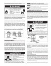
If a positive lock-up regulator is required follow these instructions:
1. Positive lock-up gas pressure regulators must be rated at or
above the input Btu/hr rating of the water heater they supply.
2. Positive lock-up gas pressure regulator(s) should be installed
no closer than 3 feet (1 meter) and no farther than 8 feet (2.4
meters) from the water heater’s inlet gas connection.
3. After installing the positive lock-up gas pressure regulator(s) an
initial nominal supply pressure setting of 7.0” W.C. while the water
heater is operating is recommended and will generally provide
good water heater operation. Some additional adjustment may
be required later to maintain a steady gas supply pressure.
4. When installing multiple water heaters in the same gas supply
system it is recommended that individual positive lock-up gas
pressure regulators be installed at each unit.
All gas piping must comply with local codes and ordinances or with
the current edition of National Fuel Gas Code (ANSI Z223.1/ NFPA-
54). Copper or brass tubing and ttings (except tin lined copper
tubing) shall not be used.
If the gas control valve is subjected to pressures exceeding 1/2 psi
(3.5 kPa), the damage to the gas control valve could result in a re
or explosion from leaking gas.
If the main gas line Shut-off serving all gas appliances is used, also
turn “off” the gas at each appliance. Leave all gas appliances shut
“off” until the water heater installation is complete.
A gas line of sufcient size must be run to the water heater.
Consult the current edition of National Fuel Gas Code
(ANSI Z223.1/NFPA 54) and your gas supplier concerning pipe
size.
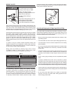
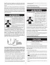
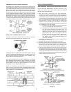
There must be:
• A readily accessible manual shut off valve in the gas supply line
serving the water heater, and
• A drip leg (sediment trap) ahead of the gas control valve to help
prevent dirt and foreign materials from entering the gas control
valve.
• A ground joint union of proper size between the shut off valve and
control valve to permit servicing of the unit.
Be sure to check all the gas piping for leaks before lighting the
water heater. Use a soapy water solution, not a match or open
ame. Rinse off soapy solution and wipe dry.
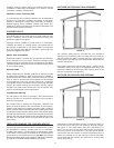
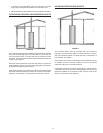
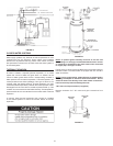
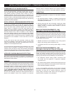
CONDENSATE PIPING
This water heater is a condensing unit and requires a drain to be
located in close proximity to allow the condensate to drain safely.
The condensate drains from the unit at the exhaust tee located at