


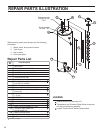
Replacement Parts
The following maintenance procedures are for the
®
Flame Guard Safety System components and
should be performed by a qualified service
technician.
Replacement parts may be ordered through your
plumber or the local distributor. Parts will be shipped at
prevailing prices and billed accordingly. When ordering
replacement parts, always have the following
information ready:
1. model, serial, and product number
2. type of gas
3. item number
4. parts description
See page 28 for a list of available repair parts.
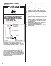
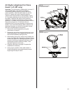
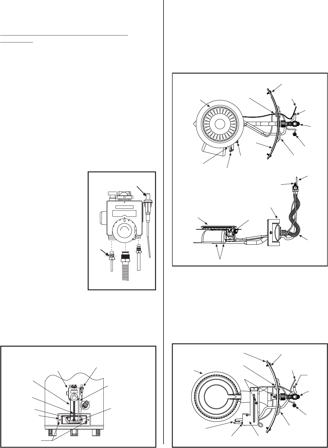
Removing the Manifold Assembly
1. Turn off the gas to the water heater at the manual
shut-off valve (Figure 3).
2. Turn the gas control knob on the combination gas
control valve/thermostat
clockwise to the “OFF”
position (Figure 19).
3. Remove the outer door.
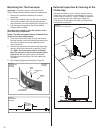
4. Remove the two screws
securing the manifold door
assembly to the skirt
(Figure 22).
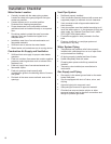
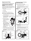
5. Disconnect the
thermocouple (left-hand
thread), pilot tube, the
igniter wire from the igniter
button, and manifold tube
at the thermostat. (Figure
21.) Note: L.P. gas
systems use reverse (left-
hand) threads on the
manifold tube.
6. Grasp the manifold tube and push down slightly to
free the manifold, pilot tube, and thermocouple.
7. Carefully remove the manifold assembly from the
burner compartment. Be sure not to damage
internal parts.
Removing the Burner from the
Manifold Assembly
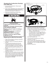
Natural Gas Burner (Low Nox)
1. Take off the burner by removing the two (2) screws
located underneath the burner.
2. Check the burner to see if it is dirty or clogged. The
burner may be cleaned with soap and hot water
(Figure 23A).
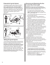
L.P. Gas Burner
1. Separate the pilot bracket from the L.P. burner by
removing screw.
2. Loosen set screw located on top of the L.P. burner
near the manifold door. Carefully, pull the burner
away from the manifold door assembly.
3. Check the burner to see if it is dirty or clogged. The
burner may be cleaned with soap and hot water
(Figure 23B).
N
O
T
W
A
H
S
T
R
E
B
O
R
I
A
C
A
V
M
R
A
W
U
T
O
H
T
H
E
R
I
S
K
O
F
Y
R
U
J
N
I
D
L
A
C
S
R
E
T
T
O
H
W
A
T
E
R
I
S
E
S
A
E
R
C
N
N
O
I
A
C
T
U N I T R O L
READ ALL INSTRUCTIONS
WARNING
BEFORE LIGHTING
Pilot
Tube
Manifold
Tube
Thermocouple
Left Hand
Thread
Figure 21
Igniter
Wire
Igniter
Button
Manifold
Screw (2)
N
O
T
W
A
H
S
T
R
E
B
O
R
I
A
C
A
V
M
R
A
W
U
T
O
H
T
H
E
R
I
S
K
O
F
Y
R
U
J
N
I
D
L
A
C
S
R
E
T
T
O
H
W
A
T
E
R
I
S
E
S
A
E
R
C
N
N
O
I
A
C
T
U N I T R O L
READ ALL INSTRUCTIONS
WARNING
BEFORE LIGHTING
Viewport
Manifold
Door
Piezo
Igniter
Button
Gas Valve /
Thermostat
Two Piece Wire
Connector
Thermocouple
Pilot Tube
Manifold
Tube
Figure 22
Burner Assembly
Removal
21
Screws
Burner
Two Piece Wire
Connector
Manifold Door
Assembly
Igniter Wire
Pilot
Tube
Manifold
Tube
Viewport
Thermocouple
Thermocouple
Retainer Clip
Pilot Assembly
Pilot Bracket
Manifold Door
Gasket
Figure 23B
L.P. Gas Burner
Assembly
Burner
Two Piece Wire
Connector
Manifold Door
Assembly
Manifold Door
Assembly
Igniter Wire
Pilot
Tube
Pilot
Tube
Manifold
Tube
Manifold
Tube
Viewport
Thermocouple
Thermocouple
Thermocouple
Retainer Clip
Pilot Assembly
Pilot Assembly
Screws
Pilot Bracket
Manifold
Door
Gasket
Figure 23A
Natural Gas (Low Nox)
Burner Assembly
Burner