


Gas Requirements
Read the data plate to be sure the water heater is
made for the type of gas you will be using in your
home. This information will be found on the data plate
located near the gas control valve. If the information
does not agree with the type of gas available, do not
install or light. Call your dealer.
Note: An odorant is added by the gas supplier to the
gas used by this water heater. This odorant may fade
over an extended period of time. Do not depend upon
this odorant as an indication of leaking gas.
Gas Piping
This gas piping must be installed according to all local
and state codes or, in the absence of local and state
codes, the “National Fuel Gas Code”, ANSI
Z223.1(NFPA 54)-latest edition.
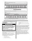
Tables 1 and 2 on page 7 are provided as a sizing
reference for commonly used gas pipe materials.
Consult the “National Fuel Gas Code” for the
recommended gas pipe size of other materials.
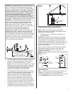
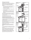
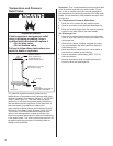
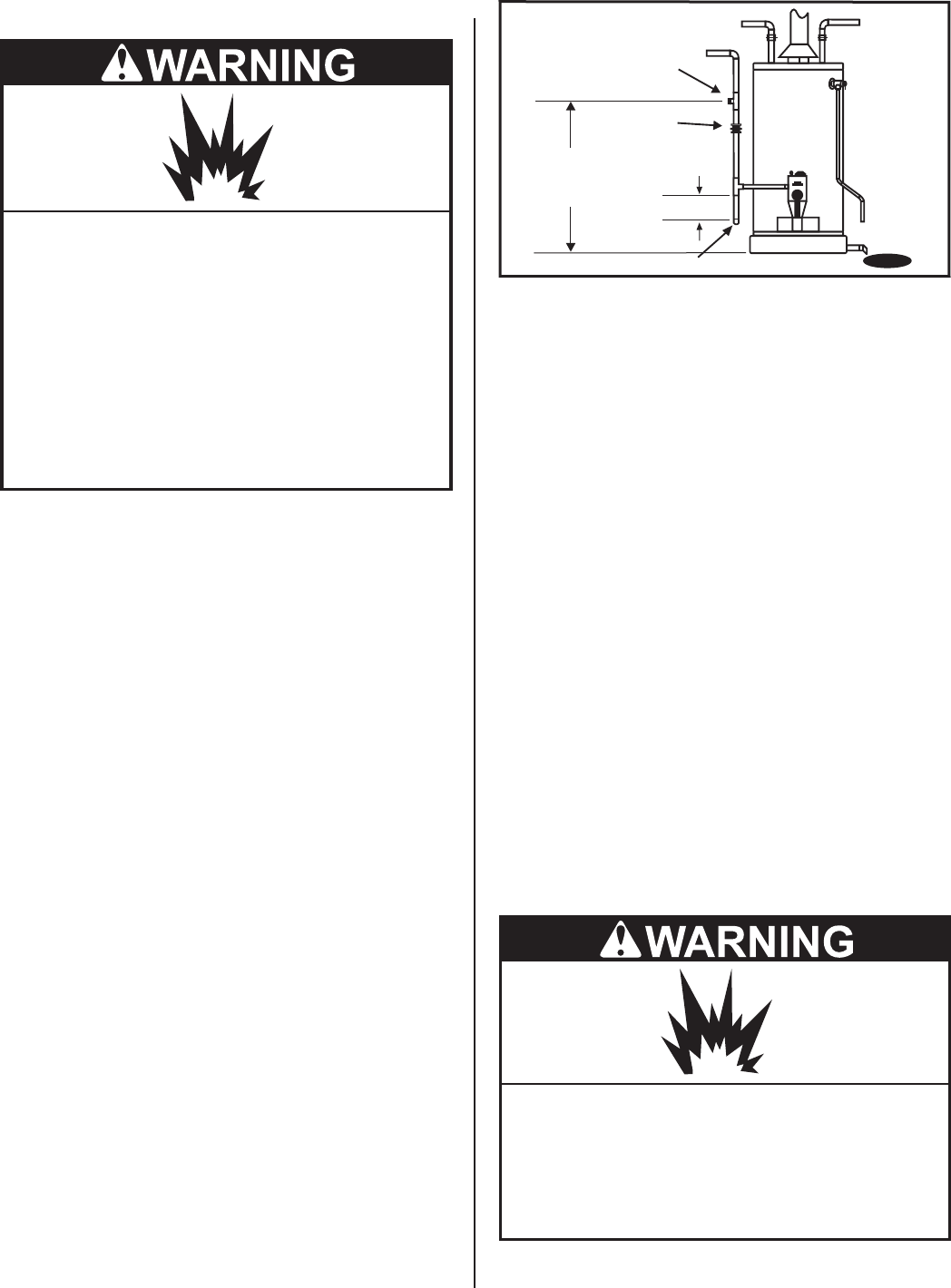
Refer to Figure 3
Note: When installing gas piping, apply approved pipe
joint compound.
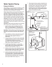
1. Install a readily accessible manual shut-off valve in
the gas supply line as recommended by the local
utility. Know the location of this valve and how to
turn off the gas to this unit.
2. Install a drip leg (if not already incorporated as part
of the water heater) as shown. The drip leg must be
no less than three inches long for the accumulation
of dirt, foreign material, and water droplets.
3. Install a ground joint union between the gas
valve/thermostat and the manual shut-off valve.
This is to allow easy removal of the gas valve/
thermostat.
4. Turn the gas supply on and check for leaks. Use a
chloride-free soap and water solution (bubbles
forming indicate a leak) or other approved method.
Gas Pressure
Important: The gas supply pressure must not exceed
the maximum supply pressure as stated on the water
heater’s data plate. The minimum supply pressure is for
the purpose of input adjustment.
Gas Pressure Testing
Important: This water heater and its gas connection
must be leak tested before placing the appliance in
operation.
!
If the code requires the gas lines to be tested at a
pressure exceeding 14” W.C., the water heater and
its manual shut-off valve must be disconnected
from the gas supply piping system and the line
capped.
!
If the gas lines are to be tested at a pressure less
than 14” W.C., the water heater must be isolated
from the gas supply piping system by closing its
manual shut-off valve.
U.L. recognized fuel gas and carbon monoxide (CO)
detectors are recommended in all applications and
should be installed using the manufacturer’s
instructions and local codes, rules, or regulations.
Note: Air may be present in the gas lines and could
prevent the pilot from lighting on initial start-up. The gas
lines should be purged of air by a qualified service
technician after installation of the gas piping system.
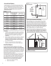
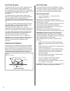
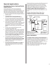
LP Gas
Gas Supply
Explosion Hazard
Use a new AGA or CSA approved gas
supply line.
Install a shut-off valve.
Do not connect a natural gas water
heater to a L.P. gas supply.
Do not connect a L.P. gas water heater to
a natural gas supply.
Failure to follow these instructions can
result in death, explosion, or carbon
monoxide poisoning.
Explosion Hazard
Have a qualified service technician make
sure L.P. gas pressure does not exceed
13” water column.
Failure to do so can result in death,
explosion, or fire.
Figure 3
Gas Piping
Manual Gas
Shut-off Valve
Ground
Joint
Union
3” min.
Check with
local utility
for min. height
Drip leg
6