


TWE-SVX03C-EN 15
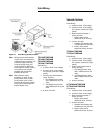
Thermostat and Control
Connections
1. Observe all notes on the
diagrams.
2. Mount the thermostat in the
desired location.
3. Install color coded low voltage
cables between outdoor unit,
indoor unit and thermostat.
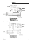
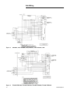
4. Connect low voltage control
wiring to the low voltage
terminal board located on the
side of the fan control box per
the typical interconnecting
wiring diagrams on pages 13
through 22.
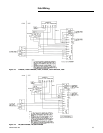
TTA090A/TWE090A
TTA120A/TWE120A
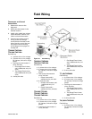
Field Wiring:
a. 3 power wires. Line voltage.
b. 3 power wires. Line voltage
for 3 phase; 2 wires for single
phase.
c. Cooling only thermostat: 3
wires, 24 volts.
i. One stage Electric heat:
add 1 additional wire, 24
volts.
ii. Two Stage Electric heat:
add 2 additional wires, 24
volts.
d. 4 wires, 24 volts.
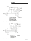
TWA090A/TWE090A
TWA120A/TWE120A
Field Wiring:
a. 3 power wires. Line voltage.
b. 3 power wires. Line voltage
for 3 phase; 2 wires for single
phase.
c. Heat pump thermostat: 6
wires, 24 volts.
i. Electric heat: add 2
additional wire, 24 volts.
d. 6 wires, 24 volts.
i. Outdoor thermostat; add
1 additional wire, 24
volts.
ii. Electric heat: add 1
additional wires, 24 volts.
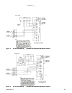
TTA120B/TTE120B
TTA120C/TWE120C
TTA120B/TWE120B
Field Wiring:
a. 3 power wires. Line voltage.
b. 3 power wires. Line voltage
for 3 phase; 2 wires for single
phase.
c. Cooling only thermostat: 4
wires, 24 volts.
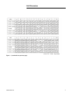
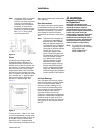
Figure 10. Field Wiring
i. One Stage Electric heat:
add 1 additional wire, 24
volts.
ii. Two Stage Electric heat:
add 2 additional wires, 24
volts.
d. 5 wires, 24 volts.
TT_060/TWE060A
Field Wiring:
a. 3 power wires. Line voltage.
b. 3 power wires. Line voltage
for 3 phase; 2 wires for single
phase.
c. Cooling only thermostat: 3
wires, 24 volts.
i. One Stage Electric heat:
add 1 additional wire, 24
volts.
ii. Two Stage Electric heat:
add 2 additional wires, 24
volts.
d. 2 wires, 24 volts.
TW_060A/TWE060A
Field Wiring:
a. 3 power wires. Line voltage
for 3 phase; 2 wires for single
phase.
Field Wiring