


10 TWE-SVX03C-EN
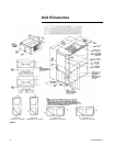
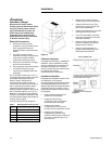
Installation Preparations
The final position for the air handler
must be dictated by required service
access to it, weight distribution over
structural supports, and by the
locations of electrical, refrigerant
and condensate drainage
connections. After this is
determined, the following
preparations should be made.
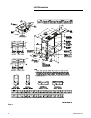
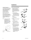
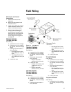
Repositioning Drain Pan
These air handlers come with one
drain pan that can be installed in any
one of four positions; this allows for
vertical or horizontal application and
right or left condensate line
connection. The drain pan can also
be easily removed for periodic
cleaning.
Note: Important! All air handlers
are shipped with the drain
pan installed in the
horizontal position and the
connection on the left side
(as shown in Figure 4). If an
alternate position is required,
the drain pan should be
repositioned before setting
the air handler.
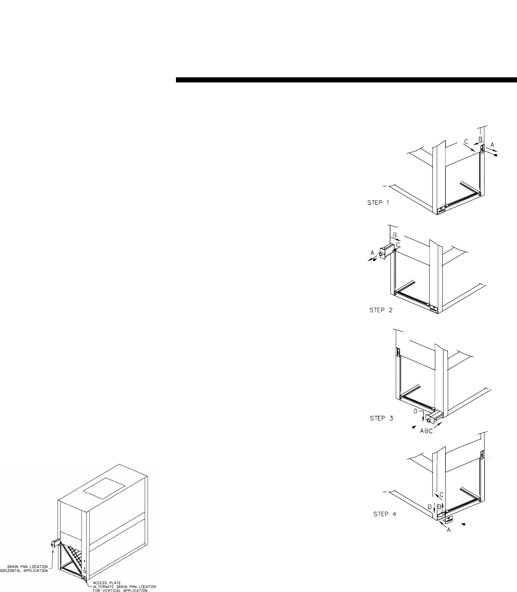
Figure 4.
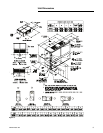
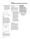
Process for Drain Pan Relocation
1. Remove the access plate at the
opposite end of the drain
connection. This plate secures
and lifts the back end of the
drain pan for sloping. It must be
removed before the drain pan
can be removed. This is done as
follows:
a. Remove the screw
b. Lift the access plate up
c. Pull the plate out. If the drain
pan is to be moved to the
vertical position also remove
the other two access plates.
2. Remove the screw securing the
drain pan.
a. Lift the pan up
b. Slide the pan out
3. Install the drain pan into the new
position.
a. Slide the drain pan into the
opening
b. Lift the drain pan up
c. Push it in all the way
d. Drop it down over the lip of
the opening, secure with
screw
4. Install the access plate on the
opposite end of the drain pain.
a. Slide the edge of the access
plate under the drain pan
b. Lift the access plate and
drain pan up
c. Push the access plate in
d. Drop the access plate down
over the lip of the opening,
secure with screw. If the
drain pan is being moved to
the vertical position, install
the other access plates over
the horizontal position
opening.
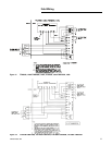
Figure 5.
Installation