


TWE-SVX03C-EN 11
Installation
Refrigerant Piping Preparation
The air handler is designed so that
refrigerant piping can enter from
either the right or left hand side. It is
shipped with the intent that the
refrigerant lines will enter from the
left hand side. To convert to right
hand entry, unbraze the elbow on the
suction line and rotate 180° and
rebraze.
Note: Important! Access to
refrigerant lines is limited in
all horizontal and some
vertical applications.
Therefore, refrigerant lines
should be stubbed out and
temporarily capped prior to
setting the air handler.
Protect adjacent surfaces
from heat damage when
brazing in and around the air
handler.
Caution
System Component Damage!
These air handlers are shipped with a
dry nitrogen holding charge in the
coil. Cut the process tube or
puncture the cap to bleed off the
nitrogen prior to any brazing.
Temporarily cap off tubes if the
refrigerant line connections are to be
made later.
Installations, Limitations and
Recommendations
The general location of the air
handler is normally selected by the
architect, contractor and/or buyer. For
proper installation the following
items must be considered.
a. Available power supply must
agree with electrical data on
component nameplate.
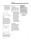
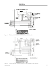
b. Air Handlers shipped wired
for 208-230 volt applications
can be converted for 460 volt
by rewiring the blower motor
(See Figure 9).
c. If external accessories are
installed on the unit,
additional clearances must be
provided.
d. All duct work should be
properly insulated to prevent
condensation and heat loss.
e. Refrigerant gas piping must
be insulated.
Caution
System Component Damage!
Properly insulate all refrigerant gas
piping to prevent possible water
damage due to condensation and to
prevent capacity loss and possible
compressor damage.
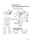
It is recommended that the outline
drawings (pages 3 and 4) be studied
and dimensions properly noted and
checked against the selected
installation site. By noting in advance
which knockouts are to be used,
proper clearance allowances can be
made for installation and possible
future service.
Note: Important! When installing
these units "free standing"
with discharge grills and
isolators, a top support with
isolator should be added to
prevent tipping. Support and
isolator can be attached to a
wall or other appropriate
structure.
Note: Important! If adding external
accessories to the unit,
additional clearances must be
considered for the overall
space needed.
For installation of accessories
available for this air handler, follow
the instructions packed with each
accessory.
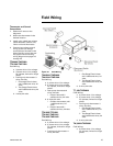
Lifting Recommendations
ƽ WARNING
Improper Unit Lift!
Test lift unit approximately 24 inches
to verify proper center of gravity lift
point. To avoid dropping of unit,
reposition lifting point if unit is not
level. Failure to properly lift unit
could result in death or serious injury
or possible equipment or property-
only damage.
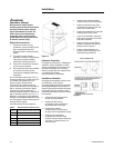
Before preparing the unit for lifting,
the center of gravity should be
determined for lifting safety. Because
of the placement of external
components, the unit weight may be
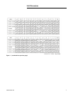
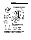
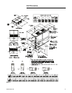
unevenly distributed. Approximate
total unit weight and corner weights
are given in Figure 1- Figure 3.
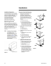
The crated unit can be moved using a
forklift of suitable capacity. For lifting
the unit into an elevated mounting
position, run lifting straps or slings
under the unit and attach securely to
the lifting device. Use spreader bars
to protect the unit casing from
damage. Test lift the unit to
determine proper balance and
stability.
Caution
Equipment Damage!
Use spreader bars to prevent straps
from damaging the unit. Install the
bars between lifting straps, both
underneath the unit and above the
unit. This will prevent the straps
from crushing the unit cabinet or
damaging the unit finish.
Horizontal Suspension
If the air handler will be suspended,
use a suspension mounting kit to
isolate the unit from the structure.
This is usually accomplished through
the use of spring or rubber isolators,
which are offered as an accessory.
Mounting rods must be field
supplied. Isolator selection is
dependent upon total unit weight
including accessories. Approximate
unit weights are provided in Table 1.