


M968650C
3
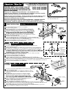
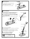
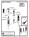
MOUNT VALVE BODIES
4
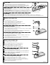
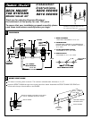
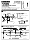
SOLDER CONNECTIONS
Insert the VALVE BODIES and TEE through the mounting
deck from below. Assemble the VALVE LOCK RINGS so
they are flush with the top of the VALVE BODIES.
Insert the HOT and COLD VALVE BODIES into the TEE. (Not
necessary for R810). The HOT VALVE BODY is
marked with a red label.
Insert the SPOUT SHANK into the TEE.
(Not necessary for R810).
Turn on the water supplies and check all connections for leakage.
Replace the GUARD on the SPOUT SHANK. Turn off the water supplies.
Solder all TEE and WATER SUPPLY CONNECTIONS.
Connect the water supply lines to the copper inlet tubes of the VALVE BODY.
Remove the GUARD from the SPOUT SHANK. Assemble the 1/4" PLUG to
the SPOUT SHANK with a thread sealant.
Tighten the VALVE BODY and SHANK MOUNTING
NUTS securely.
VALVE
LOCK RING
FITTING
MOUNTING
DECK
VALVE
LOCK RING
1/4" PLUG
SPOUT GUARD
TEE
CONNECTIONS
WATER SUPPLY
CONNECTIONS
OUTLET TUBE
(CUT AS REQUIRED)
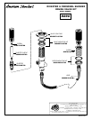
TEE
HOT
COLD
FRICTION WASHER
MOUNTING NUT
SPOUT
SHANK
Cut the copper outlet tubes of the VALVE BODIES as required.
(Not necessary for R810).
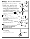
VALVE LOCK RING FLUSH WITH
TOP OF THREADS ON VALVE SHANK
VALVE
BODY
# 8 SCREWS
Fasten the VALVE LOCK RING to the wooden mounting
surface with #8 screws (not provided).
5
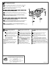
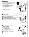
SERVICE
VALVE
LOCK NUT
SLEEVE
SCREW
VALVE
CARTRIDGE
Turn off the water supplies.
Turn HANDLE to the off position.
Unscrew the VALVE LOCK NUT and remove.
A 17mm deep socket is required.
Remove the CARTRIDGE by pulling upon the SLEEVE.
Remove the SLEEVE from the CARTRIDGE.
Remove the SPRING CLIP.
Remove the STOP WASHER. Turn it 90˚ and replace.
Replace the SPRING CLIP.
Reverse the above steps to reassembly the components.
If the spout drips, operate the handles several times
from the off to the on position. Do not force - the handles only turn 90˚
SPRING
CLIP
STOP
WASHER
90
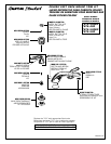
TO CHANGE THE DIRECTION OF HANDLE ROTATION
DEEP SOCKET
17mm (11/16")