


M968355D
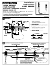
INSTALLATION
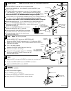
TEST
3
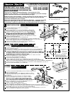
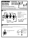
NOTE: Use thread sealant on all threaded connections.
For copper water tube installations, make two 4" long adapter nipples
( 1/2" Male NPT x 1/2" CWT ). Thread nipples into the inlet and tub
outlet of the DIVERTER BODY. Tighten connections securely. Do Not Solder
these Connections on the DIVERTER BODY. Damage may occur.
Thread HOSE (4) into the SHOWER CONNECTION (5) of the DIVERTER BODY (6)
and tighten securely. Check with local plumbing codes for backflow
prevention requirements. Install a backflow prevention device if required.
Position the DIVERTER BODY (6) as required and
tighten the MOUNTING NUT (7) securely.
Cap the HOSE OUTLET. Remove the DIVERTER GUARD.
Remove the SPOUT GUARD. Assemble the 1/4" PLUG to the SPOUT
SHANK with a thread sealant. See the R800 SERIES ROUGH VALVE KIT
instructions for details.
Turn on the water supplies.
Rotate the DIVERTER SLEEVE back and forth fully.
Check all connections for leakage.
Turn off the water supplies. Replace the DIVERTER
GUARD and the SPOUT GUARD. Remove the CAP
from the HOSE OUTLET.
1/2" COPPER WATER
TUBE INLET (MIXED
SUPPLY FROM BATH
FITTING)
HOSE OUTLET
(
MIXED SUPPL
Y
1/2" COPPER WATER
TUBE (MIXED SUPPLY
TO TUB FILLER SPOUT)
CAP
4" LONG
ADAPTER
NIPPLES
VALVE LOCK
RING FLUSH WITH
TOP OF THREADS ON
VALVE SHANK
VALVE
BODY
4
HOSE
5
6
FITTING
MOUNTING
SURFACE
S
LEEV
E
GU
AR
D
DIVERTER
GUARD
DIVERTER
SLEEVE
H
OSE
WATER INLET
T
U
B
OU
TLE
T
#8 SCREWS
#8 SCREWS
H
OSE
END
SLEEVE
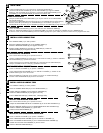
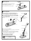
Insert the HOSE through the SLEEVE from below the mounting deck.
Thread the SLEEVE GUARD onto the HOSE END connection.
Insert the SLEEVE GUARD into the SLEEVE.
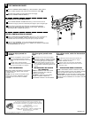
Note: Test Cap not provided.
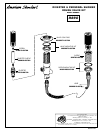
SERVICE
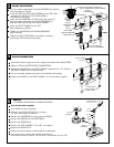
Turn off the water supplies.
Turn HANDLE to the off position.
Remove the SLEEVE from DIVERTER by losening screw.
Using 14mm (9/16") Deep Socket, remove diverter.
TO REMOVE DIVERTER
DEEP SOCKET
14mm (9/16")
SCREW
DIVERTER SLEEVE
DIVERTER
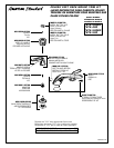
1-3/8"
Dia. HOLE
FOR HAND
SHOWER
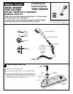
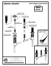
Drop the SLEEVE (1) into the hole in the mounting deck.
Assemble the WASHER (2) and LOCKNUT (3) to the SLEEVE (1) and
tighten securely.
1
2
3
5
6
7
8
Assemble MOUNTING NUT (7) and WASHER (8) onto DIVERTER BODY (6).
Connect the water inlet and tub outlet lines to
the DIVERTER BODY (6).
Fasten the VALVE LOCK RING (9) to the wooden
mounting surface with #8 screws (not provided).
Insert the DIVERTER BODY (6) through the mounting deck from below.
Assemble the VALVE LOCK RING (9) so it is flush with the top of
the DIVERTER BODY (6).
9