


23
INSTALLATION CHECKLIST
Water Heater Location
Requirements
Centrally located with the water piping system. Located
as close to the gas piping and vent pipe system as pos-
sible.
Located indoors and in a vertical position. Protected
from freezing temperatures.
Proper clearances from combustible surfaces main-
tained and not installed directly on a carpeted floor.
Sufficient room to service the water heater.
Provisions made to protect the area from water dam-
age. Properly sized drain pan installed and piped to an
adequate drain.
Installation area free of corrosive elements and
flammable materials.
Condensate Line
Drain stem is fully inserted in the elbow and glued
properly.
Trap aligned so that the exhaust pipe is in a vertical
position close to the surface of the water heater.
Line properly sloped to adequate drain or approved
condensate pump.
Properly vented.
Protected from freezing (if required).
Vent Pipe System
Vent pipe and fittings of approved material.
Acceptable size, length, and number of elbows on air
inlet pipe.
Acceptable size, length, and number of elbows on
exhaust outlet pipe.
Add the air inlet filter per the manufacturer’s instruction.
Installed in accordance with prevailing provisions of
Local codes, or in the absence of such, National Fuel
Gas Code, NFPA 54, ANSI Z223.1-Latest Edition. Ca-
nadian Installations must be performed in accordance
with CAN/CGA-B149.
All 2” horizontal piping sloped down toward the water
heater at 1/4” per foot. 3” piping sloped down towards
the heater at 1/8” per foot.
Not obstructed in any way.
Vent Termination
Horizontal
Correct relationship - outlet to inlet.
12” Min. above grade/snow level.
2” exhaust outlet/air inlet pipe sloped down towards
water heater at 1/4” per foot. 3” piping sloped down
towards the heater at 1/8” per foot.
Away from corners, other vents, windows, etc.
Alternate Horizontal
Correct relationship - outlet to inlet.
12” Min. above anticipated snow level.
2” exhaust outlet/air inlet pipe sloped down towards
water heater at 1/4” per foot. 3” piping sloped down
towards the heater at 1/8” per foot.
Away from corners, other vents, windows, etc.
Vertical
Inlet - 12” Min. above roof/snow level.
Correct relationship - outlet to inlet.
Away from corners, other vents, windows, etc.
Concentric
12” Min. above grade/snow level.
2” exhaust outlet/air inlet pipe sloped down towards
water heater at 1/4” per foot. 3” piping sloped down
towards the heater at 1/8” per foot.
Away from corners, other vents, windows, etc.
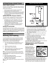
Water System Piping
Temperature and pressure relief valve properly
installed with a discharge line run to an open drain and
protected from freezing.
All piping properly installed and free of leaks.
Heater completely filled with water.
A properly sized expansion tank must be installed on all
closed systems.
A tempering valve (provided) must be installed per the
manufacturer’s instructions.
Gas Supply and Piping
If using a flexible gas connector, make sure its rating
tag matches or exceeds the input of the water heater.
Adequate pipe size and of approved material.
Gas supply is the same type as listed on the water
heater data plate.
Gas line equipped with full opening shut-off valve,
union and drip leg.
Approved pipe joint compound used.
Chloride-free soap and water solution or other ap-
proved means used to check all connections and fit-
tings for possible gas leaks.
Electrical Connections
Unit connected to a dedicated power supply.
Unit connected to a 120V electrical supply.
Proper polarity.
Water heater properly grounded.
Installed in accordance with prevailing provisions of
local codes, or in the absence of such, National Fuel
Gas Code, NFPA 54, ANSI Z223.1-Latest Edition.
Canadian installations must be performed in accor-
dance with CAN/CGA-B149.