


5
CONDENSATE LINE
Important: Do not run the condensate drain in areas
that are likely to freeze. Frozen condensate will block the
drain line and result in property damage or water heater
malfunction.
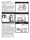
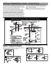
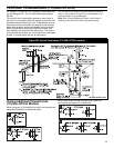
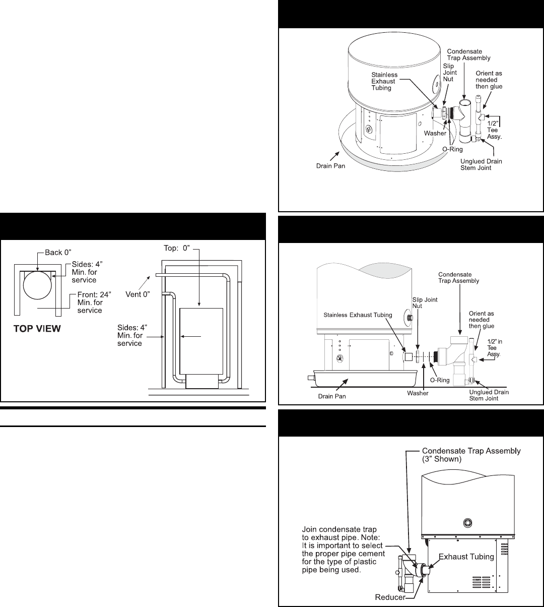
Condensate Trap Assembly
A condensate trap/drain stem assembly has been supplied
with the water heater and is located behind the access door
inside the base of the water heater. This assembly must be
installed between the water heater and the exhaust outlet
piping to ensure proper operation of the water heater. To
install, remove the slip-joint nut, stainless steel washer, and
O-ring from the trap assembly. Slip the nut, washer and
O-ring (in that order) over the stainless exhaust tubing and
slide them back near the base of the heater. Insert the trap
assembly over the tubing (see figure 3A or 3B accordingly)
and firmly hand-tighten (using a wrench will cause the
O-ring to seal improperly) the nut to form a water-tight
seal between the O-ring and the stainless exhaust tubing.
When tightened, the nut to heater base clearance should
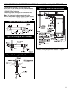
be 3/4” (+/- 1/8”). On 100 gallon models the condensate
trap assembly should be glued to the exhaust pipe (see
figure 3C).
Note: The trap should be aligned so that the exhaust pipe
is in a vertical position close to the surface of the water
heater.
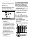
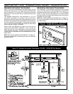
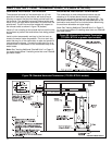
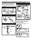
Figure 2: Minimum Clearance Locations
Figure 3A: 2” Condensation Trap Installation
100,000 - 150,000 BTU/Hr Models
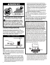
Clearances and Accessibility
Notice: Minimum clearances from combustible materi-
als are stated on the data plate located on the front of the
water heater.
• The water heater is certified for installation on a
combustible floor.
Important: If installing over carpeting, the carpeting must
be protected by a metal or wood panel beneath the water
heater. The protective panel must extend beyond the full
width and depth of the water heater by at least 3 inches
(76.2mm) in any direction or if in a alcove or closet instal-
lation, the entire floor must be covered by the panel. The
panel must be strong enough to carry the weight of the
heater when full of water.
Figure 2 may be used as a reference guide to locate the
specific clearance locations. A minimum of 24 inches of
front clearance and 4 inches on each side should be pro-
vided for inspection and service.
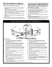
Figure 3B: 3” Condensation Trap Installation
175,000 - 199,000(50 gal.) BTU/Hr Models
Figure 3C: 3” Condensation Trap Installation
100 Gallon Models