


16
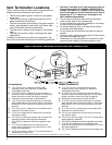
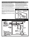
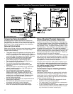
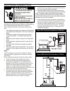
Figure 15: Typical One-Temperature System Piping Installation
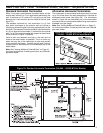
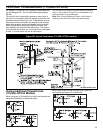
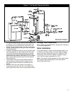
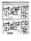
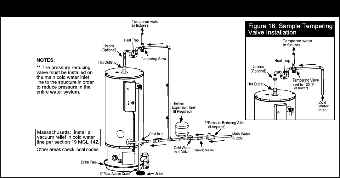
Tempering Valve Installation
A tempering valve has been provided for use with the
Polaris® Gas water heater and must be installed, per the
manufacturer’s instructions, in the domestic hot water line.
See Figure 16 for a sample tempering valve installation.
General Information
Water piping, fittings, and valves must be properly installed
for the correct and safe operation of this water heater.
Please note the following:
• The system should be installed only with piping that is
suitable for potable (drinking) water such as copper,
CPVC, or polybutylene. PVC water piping may be used
on the cold water inlet supply but not within 18 inches
of the cold water connection on the water heater.
• Do not use PVC piping on the hot water outlet,
space heating supply, or space heating return.
• Do not use any pumps, valves, or fi ttings that are
not compatible with potable water.
• Do not use valves that may cause excessive
restriction to water fl ow. Use full fl ow ball or gate
valves only.
• Do not use 50/50 tin-lead solder (or any lead based
solder) in potable water lines. Use 95/5 solder or
other equivalent material.
• Do not tamper with the thermostat, gas valve,
blower, electrical components, or temperature and
pressure relief valve. Tampering with any of the
components is dangerous and can result in death,
severe injury, or property damage. Tampering voids
all warranties. Only qualifi ed technicians should
service these components.
• Do not use this water heater as a replacement for an
existing boiler installation.
• Do not use with piping that has been treated with
chromates, boiler seal, or other chemicals.
• Do not add any chemicals to the system piping
which will contaminate the potable water supply.
Closed System/Thermal Expansion
When a backflow prevention device or check valve is
installed, it can create a “Closed System.” Heating water
in a closed system causes normal thermal expansion and
increases pressure in the water system. When this pres-
sure reaches 150 psi, it triggers the safety system in the T
& P Relief Valve. This can result in the relief valve releas-
ing water during every cycle. The rapid and repeated
expansion and contraction of the water heater components
and the system piping can cause premature failure of the
relief valve, as well as the water heater itself. Replacing
the relief valve will not correct the problem.
If the water heater is installed in a closed water supply sys-
tem, such as one having a backflow preventer in the cold
water supply line, means shall be provided to control ther-
mal expansion. Contact the water supplier or local plumb-
ing inspector on how to control this situation.
A properly sized expansion tank must be installed to pre-
vent the water pressure from building to such a level in a
Closed System. The manufacturer of this water heater
will void the warranty if there is a failure to install a
properly sized expansion tank.
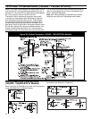
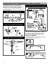
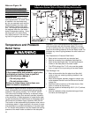
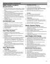
Combination Space Heating/Potable
Water System
Some water heater models are equipped with inlet/outlet
connections for use in space heating applications. If this
water heater is to be used to supply both space heating
and potable (drinking) water, the instructions listed below
must be followed (see fi gure 17).
• Be sure to follow the manual(s) shipped with the air
handler or other type heating system.
• This water heater is not to be used as a replacement
for an existing boiler installation.
• Do not use with piping that has been treated with chro-
mates, boiler seal or other chemicals and do not add
any chemicals to the water heater piping.
*100 Gallon Model Shown.