


7
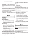
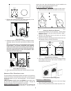
CLIPS
SELF-DRILLING
SCREWS
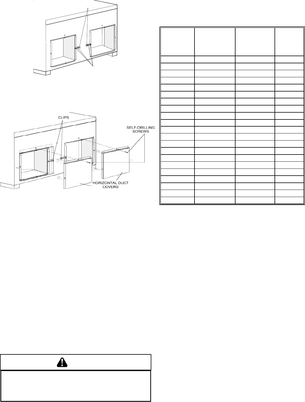
Cover Clip Installation
3. Attach 16x16 horizontal covers using screws provided with
kit to the outer duct opening flange and cover clip holes.
4. Secure the center of the top flat cover flange to the unit
using a self-drilling screw included with the unit.
Horizontal Duct Cover Installation
DUCTWORK
Duct systems and register sizes must be properly designed for the
C.F.M. and external static pressure rating of the unit. Ductwork should
be designed in accordance with the recommended methods of Air
Conditioning Contractors of America Manual D (Residential) or
Manual Q (Commercial). All ductwork exposed to the outdoors must
include a weatherproof barrier and adequate insulation.
A duct system should be installed in accordance with Standards of
the National Board of Fire Underwriters for the Installation of Air Con-
ditioning, Warm Air Heating and Ventilating Systems. Pamphlets No.
90A and 90B.
The warm air supply duct from the unit through a wall fabricated of
combustible material may be installed without clearance. However,
minimum clearances for the unit must be observed (see appendix in
back of manual).
The outlet duct should be provided with an access panel.
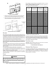
For vertical airflow, the ductwork should be attached to the roof curb
prior to installing the unit. Ductwork dimensions are shown in the
Amana
®
PRC roof curb installation manual.
If desired, supply and return duct connections to the unit may be
made with flexible connections to reduce possible unit operating
sound transmission.
FILTERS
WARNING
T
O AVOID PROPERTY DAMAGE
,
PERSONAL INJURY OR DEATH, DISCONNECT
ELECTRICAL POWER BEFORE REMOVING FILTERS.
N
EVER OPERATE FURNACE
WITHOUT A FILTER INSTALLED BECAUSE DUST AND LINT WILL BUILD UP ON
INTERNAL PARTS RESULTING IN LOSS OF EFFICIENCY, EQUIPMENT DAMAGE
AND POSSIBLE FIRE.
Even though a return air filter is not supplied with this unit, there
must be a means of filtering all return air.
Refer to the following table or the Product Data Book applicable to
your model* for filter size information.
MODEL
DISPOSABLE
FILTER (ft
2
)
1
PERMANENT
FILTER (ft
2
)
2
RATED
COOLING
AIRFLOW
(CFM)
PHB24C02* 3.0 1.5 850
PHB30C02* 3.4 1.7 960
PHB36C02* 4.0 2 1170
PHB42C02* 4.5 2.3 1350
PHB48C02* 5.5 2.8 1550
PHB60C02* 6.5 3.3 1750
PHB24CC2* 3.0 1.5 850
PHB30CC2* 3.4 1.7 960
PHB36CC2* 4.0 2 1170
PHD24C02* 3.0 1.5 810
PHD30C02* 3.4 1.7 1020
PHD36C02* 3.0 1.5 1100
PHD42C02* 3.4 1.7 1200
PHD48C02* 5.5 2.8 1550
PHD60C02* 6.5 3.3 1750
PHD24CC2* 3.0 1.5 810
PHD30CC2* 3.4 1.7 1020
PHD36CC2* 4.0 2 1100
1
Based on a face velocity of 300 ft./min.
2
Based on a face velocity of 600 ft./min.
If using the Over/Under Transition Kit, the filter(s) may be located in
the return air duct(s) or return air filter grille(s). Filters installed exter-
nal to the unit should be sized in accordance with their manufacturer
recommendations. A throwaway filter must be sized for a maximum
face velocity of 300 feet per minute.
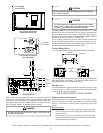
FILTER INSTALLATION
Important: When installing a filter, the air flow arrows on the filter
must point toward the circulating air blower.
CONDENSATE DRAIN
CONDENSATE DRAIN CONNECTION
An external condensate drain trap is required with this unit. See
your distributor for details. For proper unit operation, the trap must
be filled either before a cooling startup or during a unit “cycle-off”
after 20 minutes of running on first cycle. This drain can be ex-
tended using 3/4” PVC piping.
*NOTE: Please contact your distributor or our website for the applicable product data book referred to in this manual.