ENGLISH
USER MANUAL
6
1463388000(1)2008-05 A SR 1301 P
MACHINE DESCRIPTION
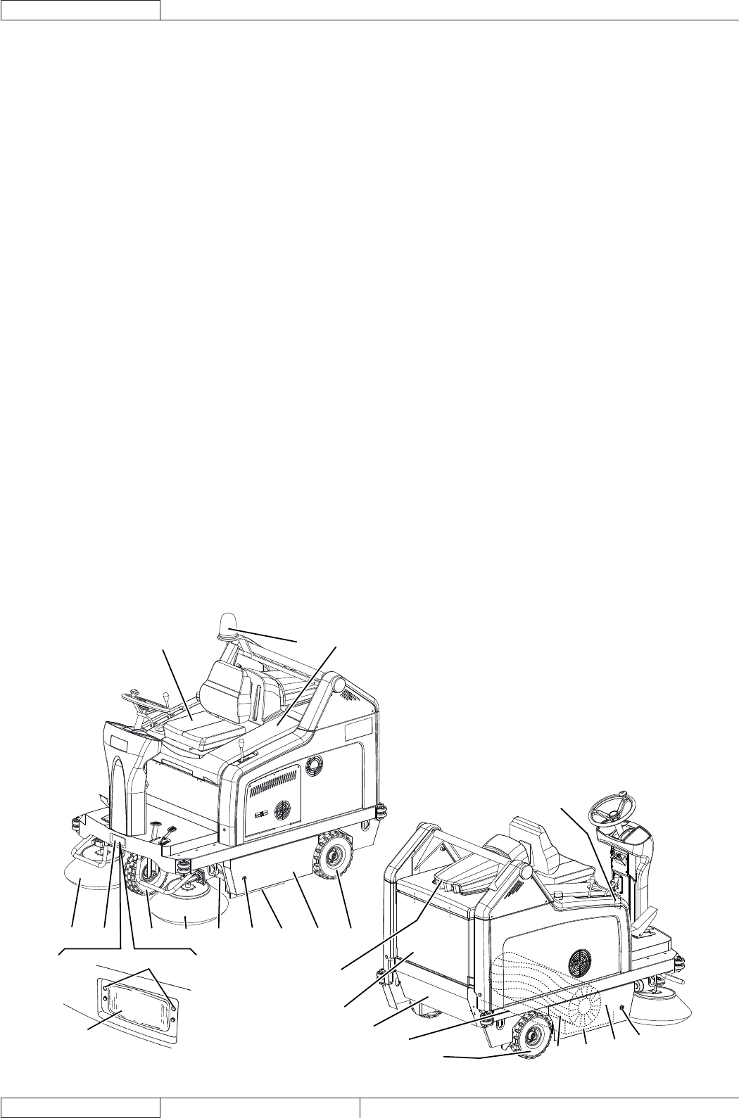
MACHINE STRUCTURE
21
9
10 9 15 11 18 6 16 5 14
3
20
4
19
14
12
17
7
8
1
13254
P100206
Serial number plate/technical data/conformity certifi cation1.
Flashing light (always on when the ignition key is turned to 2.
“I”) (optional)
Vacuum system motor cover3.
Hopper (empty it when it is full)4.
Left door (to be opened for performing maintenance 5.
procedures only)
Left closing fastener with safety mounting screw6.
Right door (for main broom removal)7.
Right fastener8.
Working light (optional)9.
Right side broom10.
Left side broom (optional)11.
Main broom12.
Engine compartment hood13.
Rear driving wheels on fi xed axle14.
Front steering wheel15.
Left side skirt16.
Right side skirt17.
Front skirt18.
Rear skirt19.
Dust fi lter container20.
Working light aiming adjusting screws21.
Engine exhaust manifold22.
Engine compartment hood (open)23.
Battery24.
Lamellar fuse box25.
Vacuum system motor connector26.
Drive system pump27.
Drive system oil tank28.
Petrol engine29.
Fuel tank30.
Fuel fi ller cap31.
Engine air fi lter32.
Petrol engine model and serial number33.
Engine oil level plug34.
Engine oil fi ller plug35.
Dynamotor36.
Hydraulic pump release screw (for machine pushing/37.
towing when the drive system is not available)
Engine oil drain plug38.
Engine start relay39.
Engine oil drain hose40.
Hopper hydraulic lifting system oil tank41.
Hopper lifting pump drive relay42.
Drive system motors43.
Petrol engine guard44.
Guard mounting screws
45.
Guard fasteners46.
Left side bulkhead47.
Bulkhead mounting screws48.
Bulkhead fasteners49.
Charging system fuse50.
Spark plug51.
Engine silencer52.
Engine exhaust end pipe53.
Driver’s seat54.
Hood support rod55.
Diode56.
Battery connection diagram57.


