


13
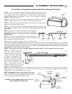
INSTALLATION OF ALL-CLEAR PHOTOSYSTEM:
STEP 1:
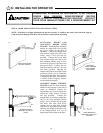
Mark the position of the ALL-CLEAR™ Photosystem as follows: Mark a line on the left and right door jamb (close
to the door track) FOUR (4) inches AND SIX (6) inches above the floor. The top mark is the maximum height and the bottom line is
the minimum height that the photosystem accessory can be placed.
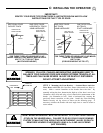
STEP 2: Mount the Photosystem "L" Brackets as follows:
A. Remove the four mounting brackets from the package. Temporarily place the "U" shaped brackets, one around the receiver (unit
with window and red LED) and one around the transmitter. NOTE: It is easier to slip the photosystem units in from the side of
the bracket than forcing them in from the front of the bracket.
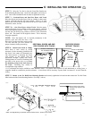
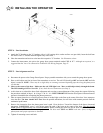
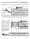
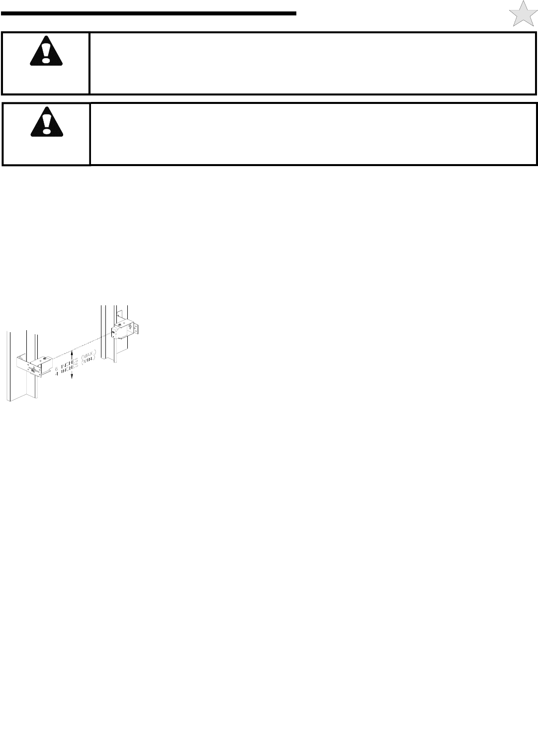
B. Your photosystem assembly is provided with a universal bracket set. Using either the
transmitter or receiver (window up towards the ceiling), hold the "L" bracket and the "U"
bracket set together while moving them in between the limit marks on the door jamb. Continue
to move the photosystem assembly within the limit marks until it clears the door hardware. See
Illustration, left. Check to ensure the WINDOW ON THE FRONT OF THE
PHOTOSYSTEM UNIT IS WITHIN THE LIMIT MARKS ON THE DOOR JAMB.
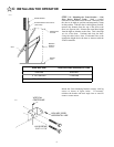
C. Place a mark in the center of the lag screw elongated mounting hole. Measure its position
and place a similar mark on the opposite door jamb. The brackets may be temporarily mounted to the jamb with a 1"
flat head nail (provided) using the small hole above the slot. Using two 5/16" X 1-1/2” lag screws (provided),
permanently mount the "L" bracket to both door jambs.
STEP 3: Connect the Photosystem as follows:
A. Remove the transmitter and receiver from their "U" mounting brackets.
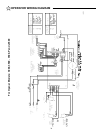
Refer to Page 21 for various wiring options for the All-Clear™ Photosystem. Steps B and C, below, describe the wiring for
Series Connection with Receiver First, as illustrated on Page 21.
B. Run a wire pair (not supplied) around the garage door jamb between the transmitter and receiver "L" mounting brackets.
NOTE: Leave about 12” of extra wire at each end. Use a minimum 22 gauge solid "trace" wire for interconnect.
C. Run a wire pair (20 or 22 gage solid wire) from the receiver position (unit with "LED" light in the front, may be either side of
the door) back to the rear bulkhead of the garage door opener. NOTE: Leave about 12” of extra wire at the receiver end and
about 24” of extra wire at the opener end.
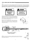
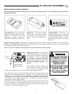
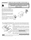
D. Using the Strip Gage on the side of each unit as a guide, strip 5/16” from each wire end at the photosystem units.
E. Slip the wires into the Quick Wire holes marked T1 & T2 on the transmitter and connect to the Quick Wire holes marked T1 &
T2 on the receiver. Although not required, it is suggested that the "trace" be connected to T1. Insert the remaining two wires at
the receiver end to Quick Wire holes marked B & C on the receiver. Although not required, it is suggested that the "trace" be
connected to Terminal B. See Wiring Diagram, page 21.
NOTE: IF NECESSARY, WIRE ENDS CAN BE REMOVED FROM AND REINSERTED INTO THE QUICK WIRE HOLES A
MAXIMUM OF THREE TIMES. TO REMOVE WIRE FROM THE QUICK WIRE HOLES, INSERT A SMALL SCREWDRIVER
NO NARROWER THAN 1/8” INTO THE SLOT ABOVE THE HOLE AND PULL THE WIRE OUT. THE WIDEST POSSIBLE
SCREW DRIVER TIP WHICH WILL FIT INTO THE SLOT SHOULD BE USED. A HEAD NARROWER THAN 1/8” CAN
DAMAGE THE QUICK WIRE TERMINAL.
104382
D: AUXILIARY EQUIPMENT
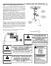
WARNING
RISK OF ENTRAPMENT.
DISCONNECT POWER TO THE OPENER BEFORE AND DURING INSTALLATION OF
THIS ACCESSORY. DO NOT RECONNECT POWER TO OPENER UNTIL INSTRUCTED
TO DO SO. ENSURE DOORWAY IS CLEAR BEFORE STARTING TESTING OF UNIT.
AN AUTOMATIC GARAGE DOOR SYSTEM POSES A THREAT OF INJURY OR EVEN
DEATH. INSTALL THE ALL-CLEAR PHOTOSYSTEM NO HIGHER THAN 4” - 6”
ABOVE THE GARAGE FLOOR TO REDUCE THE RISK TO SMALL CHILDREN.
WARNING