


506468-01 Issue 1004 Page 3
NOTE: Elevation of the unit may be accomplished by
constructing a frame using suitable materials. If a
support frame is constructed, it must not block drain
holes in unit base.
• When installed in areas where low ambient tempera-
tures exist, locate unit so winter prevailing winds do
not blow directly into outdoor coil.
• Locate unit away from overhanging roof lines which would
allow water or ice to drop on, or in front of, coil or into unit.
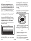
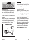
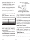
Slab Mounting
When installing a unit at grade level, install on level slab
high enough above grade so that water from higher ground
will not collect around the unit (see Figure 2).
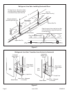
Roof Mounting
Install unit at a minimum of 6" above surface of the roof to
avoid ice buildup around the unit. Locate the unit above a
load bearing wall or area of the roof that can adequately
support the unit. Consult local codes for rooftop applications.
Electrical Wiring
All field wiring must be done in accordance with the
National Electrical Code (NEC) recommendations,
Canadian Electrical Code (CEC) and CSA Standards, or
local codes, where applicable.
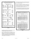
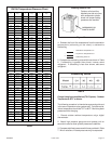
Refer to the furnace or blower coil Installation Instructions
for additional wiring application diagrams and refer to unit
rating plate for minimum circuit ampacity and maximum
overcurrent protection size.
1. Install line voltage power supply to unit from a properly
sized disconnect switch. Any excess high voltage field
wiring should be trimmed or secured away from the
low voltage field wiring.
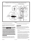
2. Ground unit at unit disconnect switch or to an earth
ground. To facilitate conduit, a hole is in the bottom of the
control box. Connect conduit to the control box using a
proper conduit fitting. Units are approved for use only with
copper conductors. 24V Class II circuit connections are
made in the low voltage junction box. A complete unit
wiring diagram is located inside the unit control box cover
(see also page 26 of this instruction).
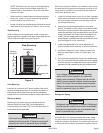
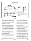
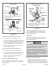
3. Install room thermostat on an inside wall that is not
subject to drafts, direct sunshine, or other heat sources.
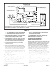
4. Install low voltage wiring from outdoor to indoor unit
and from thermostat to indoor unit (see Figure 3 on
page 4).
5. Do not bundle any excess 24V control wire inside control
box. Run control wire through installed wire tie and tighten
wire tie to provide low voltage strain relief and to maintain
separation of field-installed low and high voltage circuits.
Line voltage is present at all components
when unit is not in operation on units with
single pole contactors. Disconnect all remote
electric power supplies before opening access
panel. Unit may have multiple power supplies.
Failure to disconnect all power supplies could
result in personal injury or death.
WARNING
Refrigerant Piping
Unit must be grounded in accordance with
national and local codes. Failure to ground unit
properly can result in personal injury or death.
WARNING
Figure 2
Slab Mounting
Discharge Air
Mounting Slab
Ground Level
Building
Structure
Refrigerant can be harmful if inhaled. Refrigerant
must always be used and recovered responsibly.
Incorrect or irresponsible use of refrigerant can
result in personal injury or death.
WARNING
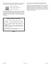
If the 4HP16LT unit is being installed with a new indoor
coil and line set, the refrigerant connections should be
made as outlined in this section. If an existing line set and/
or indoor coil will be used to complete the system, refer to