


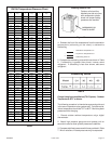
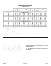
Defrost Temperature Termination Shunt (Jumper)
Pins—The defrost board selections are: 50, 70, 90, and
100°F (10, 21, 32 and 38°C). The shunt termination pin is
factory set at 50°F (10°C). If the temperature shunt is not
installed, the default termination temperature is 90°F
(32°C).
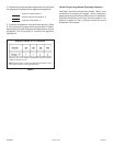
DELAY MODE
The defrost board has a field-selectable function to
reduce occasional sounds that may occur while the unit is
cycling in and out of the defrost mode. When a jumper is
installed on the DELAY pins, the compressor will be
cycled off for 30 seconds going in and out of the defrost
mode. Units are shipped with jumper installed on DELAY
pins.
NOTE - The 30 second off cycle is NOT functional
when jumpering the TEST pins.
OPERATIONAL DESCRIPTION
The defrost control board has three basic operational
modes: normal, calibration, and defrost.
Normal Mode—The demand defrost board monitors the
O line, to determine the system operating mode (heat/
cool), outdoor ambient temperature, coil temperature
(outdoor coil) and compressor run time to determine
when a defrost cycle is required.
Calibration Mode—The board is considered uncalibrated
when power is applied to the board, after cool mode
operation, or if the coil temperature exceeds the
termination temperature when it is in heat mode.
Calibration of the board occurs after a defrost cycle to
ensure that there is no ice on the coil. During calibration,
the temperature of both the coil and the ambient sensor
are measured to establish the temperature differential
which is required to allow a defrost cycle.
Defrost Mode—The following paragraphs provide a
detailed description of the defrost system operation.
DETAILED DEFROST SYSTEM OPERATION
Defrost Cycles—The demand defrost control board
initiates a defrost cycle based on either frost detection or
time.
! Frost Detection—If the compressor runs longer than
30 minutes and the actual difference between the
clear coil and frosted coil temperatures exceeds the
maximum difference allowed by the control, a defrost
cycle will be initiated.
IMPORTANT - The demand defrost control board
will allow a greater accumulation of frost and will
initiate fewer defrost cycles than a time/
temperature defrost system.
! Time—If 6 hours of heating mode compressor run
time has elapsed since the last defrost cycle while the
coil temperature remains below 35°F (2°C), the
demand defrost control will initiate a defrost cycle.
Actuation—When the reversing valve is de-energized,
the Y1 circuit is energized, and the coil temperature is
below 35°F (2°C), the board logs the compressor run
time. If the board is not calibrated, a defrost cycle will be
initiated after 30 minutes of heating mode compressor run
time. The control will attempt to self-calibrate after this
(and all other) defrost cycle(s).
Calibration success depends on stable system
temperatures during the 20-minute calibration period. If
the board fails to calibrate, another defrost cycle will be
initiated after 45 minutes of heating mode compressor run
time. Once the defrost board is calibrated, it initiates a
demand def rost cycle when the difference between the
clear coil and frosted coil temperatures exceeds the
maximum difference allowed by the control OR after 6
hours of heating mode compressor run time has been
logged since the last defrost cycle.
NOTE - If ambient or coil fault is detected, the board
will not execute the “TEST” mode.
Termination—The defrost cycle ends when the coil
temperature exceeds the termination temperature or after
14 minutes of defrost operation. If the defrost is
terminated by the 14-minute timer, another defrost cycle
will be initiated after 30 minutes of run time.
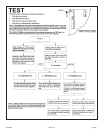
Test Mode—When Y1 is energized and 24V power is
being applied to the board, a test cycle can be initiated by
placing the termination temperature jumper across the
“Test” pins for 2 to 5 seconds. If the jumper remains
across the “Test” pins longer than 5 seconds, the control
will ignore the test pins and revert to normal operation.
The jumper will initiate one cycle per test.
Enter the “TEST” mode by placing a shunt (jumper)
across the “TEST” pins on the board after power-up.
(The “TEST” pins are ignored and the test function is
locked out if the shunt is applied on the “TEST” pins
before power-up). Board timings are reduced, the low-
pressure switch is ignored and the board will clear any
active lockout condition.
Each test pin shorting will result in one test event.
For each “TEST” the shunt (jumper) must be removed for
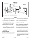
at least 1 second and reapplied. Refer to flow chart for
“TEST” operation.
Note: The Y1 input must be active (ON) and the “O”
room thermostat terminal into board must be
inactive.
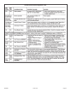
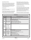
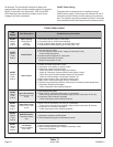
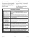
DEFROST BOARD DIAGNOSTICS
See defrost control board diagnostic LED table on next
page to determine defrost board operational conditions
and to diagnose cause and solution to problems.
506468-01 Page 19Issue 1004