


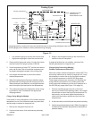

DEFROST BOARD PRESSURE SWITCH
CONNECTIONS
The unit’s automatic reset pressure switches (LO PS -
S87 and HI PS - S4) are factory-wired into the defrost
board on the LO-PS and HI-PS terminals, respectively.
(OPTIONAL) Low Pressure Switch (LO-PS) — When
the low pressure switch trips, the defrost board will cycle
off the compressor, and the strike counter in the board
will count one strike. The low pressure switch is ignored
under the following conditions:
! during the defrost cycle and 90 seconds after the
termination of defrost
! when the average ambient sensor temperature is below
15° F (-9°C)
! for 90 seconds following the start up of the compressor
! during “test” mode
High Pressure Switch (HI-PS) — When the high
pressure switch trips, the defrost board will cycle off the
compressor, and the strike counter in the board will count
one strike.
DEFROST BOARD PRESSURE SWITCH SETTINGS
High Pressure (auto reset) - trip at 590 psig; reset at
418.
Low Pressure (auto reset) - trip at 25 psig; reset at 40.
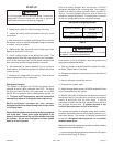
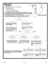
5-STRIKE LOCKOUT FEATURE
The internal control logic of the board counts the pressure
switch trips only while the Y1 (Input) line is active. If a
pressure switch opens and closes four times during a Y1
(Input), the control logic will reset the pressure switch trip
counter to zero at the end of the Y1 (Input). If the
pressure switch opens for a fifth time during the current
Y1 (Input), the control will enter a lockout condition.
The 5-strike pressure switch lockout condition can be
reset by cycling OFF the 24-volt power to the control
board or by shorting the TEST pins between 1 and 2
seconds. All timer functions (run times) will also be reset.
If a pressure switch opens while the Y1 Out line is
engaged, a 5-minute short cycle will occur after the switch
closes.
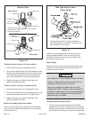
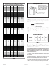
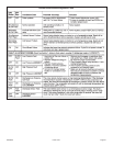
DEFROST SYSTEM SENSORS
Sensors connect to the defrost board through a field–
replaceable harness assembly that plugs into the board.
Through the sensors, the board detects outdoor ambient,
coil, and discharge temperature fault conditions. As the
detected temperature changes, the resistance across the
sensor changes. Sensor resistance values can be
checked by ohming across pins .
NOTE - When checking the ohms across a sensor, be
aware that a sensor showing a resistance value that
is
not within the range shown, may be performing as
designed. However, if a shorted or open circuit is
detected, then the sensor may be faulty and the
sensor harness will needs to be replaced.
Coil Sensor—The coil temperature sensor considers
outdoor temperatures below -35°F (-37°C) or above
120°F (48°C) as a fault. If the coil temperature sensor is
detected as being open, shorted or out of the temperature
range of the sensor, the board will not perform demand or
time/temperature defrost operation and will display the
appropriate fault code. Heating and cooling operation will
be allowed in this fault condition.
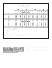
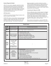
Sensor
Temperature
Range °F (°C)
Red Led (DS1)
Outdoor
(Ambient)
Coil
Discharge (If
applicable)
Note: Sensor resistance decreases as sensed temperature increases.
Pins/Wire
Color
-35 (-37 to 120
(48)
280,000 to 3750
3 & 4
(Black)
-35 (-37) to 120
(48)
280,000 to 3750
24 (-4) to 350
(176)
41,000 to 103
5 & 6
(Brown)
1 & 2
(Yellow)
Sensor Temp. / Resistance Range
Ambient Sensor—The ambient sensor considers
out
door temperatures below -35°F (-37°C) or above
120°F (48°C) as a fault. If the ambient sensor is detected
as being open, shorted or out of the temperature range of
the sensor, the board will not perform demand defrost
operation. The board will revert to time/temperature
defrost operation and will display the appropriate fault
code. Heating and cooling operation will be allowed in this
fault condition.
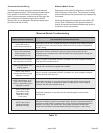
NOTE - Within a single room thermostat
demand, if 5-strikes occur, the board will lockout
the unit. Defrost board 24 volt power “R” must
be cycled “OFF” or the “TEST” pins on board
must be shorted between 1 to 2 seconds to reset
the board.
506468-01 Page 18Issue 1004