


H
ELECTRICAL SYSTEMS
H - 13
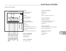
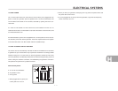
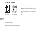
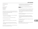
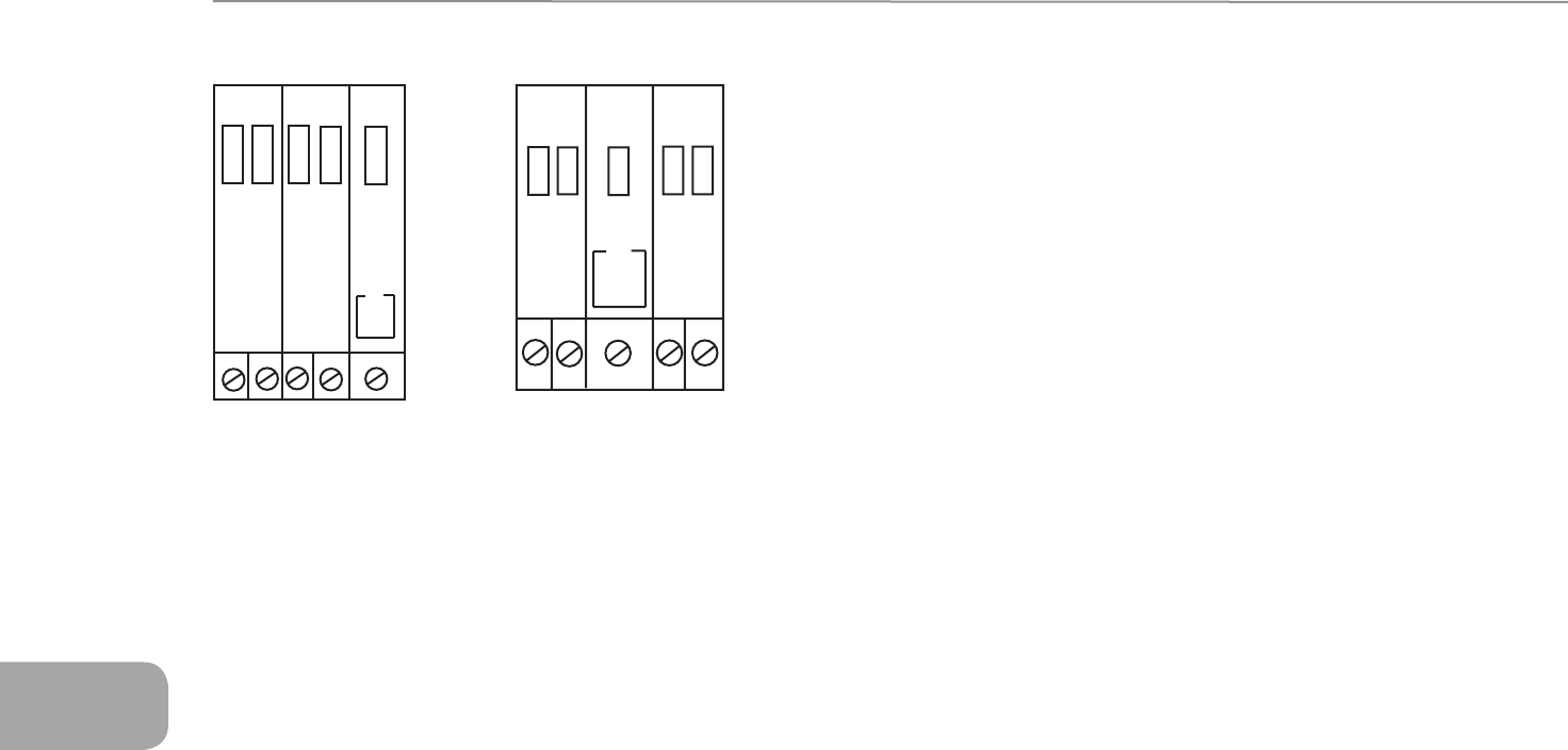
110-Volt Circuit Diagram
MID BATH REAR BATH
Circuit 1. 30 Amp, Main Circuit 1. 30 Amp, Main
Circuit 2. 20 Amp, AES Circuit 2. 20 Amp, Converter
Circuit 3. 20 Amp , TV, Convertor Circuit 3. 20 Amp , Refer, Galley, Outside
Receptacles
Circuit 4, 20 Amp, Unused Circuit 4, 20 Amp, AES
Circuit 5, 20 Amp, Refer, Galley, Circuit 5, 20 Amp, Receptacles
Outside Receptacles
There are five 110-volt breakers.
Their functions are:
Main: All 110 voltage flows through this breaker to the other four breakers. Shutting off
this breaker will shut down all 110 systems
Converter: This circuit supplies power to operate the converter and its functions.
GFI One of the breakers is a GFI (Ground Fault Interrupter) breaker. The intent of this
breaker is to sense any loss of ground before a harmful shock could occur, and kick
the breaker out. These sensitive breakers are installed in the circuit feeding the outside
receptacle, and galley area. These are the areas where the use of water or the wet
ground could put a person in danger of shock. Since the GFI breaker is so sensitive, it
is not unusual to have it kick out for no apparent reason. To reset a GFI you must first
push the lever down slightly before resetting the breaker. This breaker supplies power
to the exterior 110-volt outlet and the galley outlet.
AES: This breaker supplies power to the Automatic Energy Selector Switch. The
microwave and roof air conditioner are both wired into this switch. Both appliances
cannot be operated at the same time on the circuit. The AES prioritizes the power to
the roof AC. If the microwave is used, the switch will cut power to the roof AC and
supply power to the microwave. Once the microwave is turned off, power is restored
to the AC.
Receptacles: This breaker supplies power to the refrigerator and entertainment center
outlets.
30
20
20
20
20
TEST
1 2
3
4
5
30
20
20
20
20
1
2
3
4 5
TEST