


8. Align the inlet screw holes with the mounting plate holes and lightly press
the inlet into place, guiding any extra wire back through the mounting plate
as you go. Attach wall inlet to mounting plate with provided screws making
sure mounting plate is properly seated in hole (Figure 12).
NOTE: Do not cement wall inlet to mounting plate, the built in mounting plate
gasket will provide a positive seal.
Installing the Tubing
NOTE: When installing the tubing, start at the farthest inlet and work towards
the power unit. Keep the tubing as straight as possible with the least amount
of elbows and tees as possible to ensure maximum performance of your system.
When installing tees or elbows, make sure the curve in the fitting is aligned so
that the air flow is towards the power unit.
1. Measure the length of tubing needed to connect into the main trunk line,
adding approximately 3/4" of tubing for insertion into fittings.
2. Cut the tubing, taking care to keep the straight square edge. The use of a
miter box is recommended (Figure 6).
3. Remove rough edges with a utility knife or coarse sand paper (Figure 7).
4. Dry fit all pieces and ensure proper fit and alignment before cementing.
5. When dry fitting tubing, run low voltage wire (18 gauge, two conductor) by
securing to tubing with tape. Allow approximately 6" of excess wire for
connection to each inlet (Figure 8).
NOTE: PVC solvent cement “welds” the fitting to the tubing through a chemical
reaction to produce an air tight seal. It is important to make sure all surfaces
are clean and free of burrs to ensure a proper seal.
6. Once all tubing has been cut, cleaned, and checked for fit, apply model
CVFA35 PVC cement (not included) or equivalent cement to the outside of
the tubing covering about 1". DO NOT allow any of the cement to enter the
inside of the tubing (Figure 9).
7. Insert tubing with cement into fitting with a twisting motion to ensure the
cement has been evenly spread. Check that the tubing is evenly seated in
the fitting and is aligned properly with the rest of the line (Figure 10).
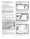
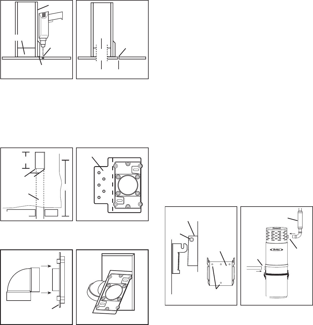
Installing the Power Unit
1. Determine a mounting location within 5 feet of a grounded electrical outlet
and install the included mounting bracket (located inside of collection
canister during shipping) using at least two appropriate screws (not included)
for the wall material (Figure 21). The bracket must be level and mounted
high enough to allow a minimum of 18" from the floor to the bottom of the
collection canister.
2. Hang power unit on bracket so that it is properly seated between the two
brackets of the power unit and tighten cross bolt (Figure 21).
3. Make tubing connections by cementing intake tubing (from the inlets) to
the intake valve and connecting exhaust tubing to the exhaust valve. An
optional model AKCVM1 sound muffler (not included) can be installed to
the exhaust tubing to reduce the sound of the exhaust air (Figure 22).
NOTE: Exhaust should not be vented into a wall, ceiling, or concealed space
within the home. It is best to exhaust to the outdoors.
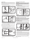
Installation into Existing Construction
Installing the Inlet Valves
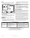
1. Once the desired location of the inlet has been determined, drill a small pilot
hole through the subfloor directly below the center of the inlet and as close
to the wall as possible (Figure 15).
2. From below, locate the pilot hole and measure over approximately 2-1/4"
(1/2" for the drywall + 1-3/4" to the center of a standard 2" x 4" sole plate).
Add extra for any additional material such as baseboards, thicker drywall,
etc. Using a 2-1/2" hole cutter, drill through flooring and sole plate. Using a
flashlight, inspect the interior of the wall to confirm that there are no
obstructions (Figure 16).
NOTE: Installation height will depend on personal preference, but generally the
inlet is installed 18" above the finished floor.
3. After confirming that there are no obstructions within the wall, cut a 2-1/2"
x 4-3/8" hole in the wall at the desired wall inlet location (Figure 17).
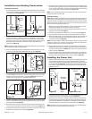
4. Remove the perforated section of the mounting plate (Figure 18) and cement
a model CVFE90S short 90° elbow to the mounting plate, facing the correct
direction to make the connection to the tubing (Figure 19) (see step 7 in
Installing the Tubing section for cementing instructions).
5. Tape the low voltage wire (minimum, solid 18 gauge, two conductor) to the
end of a sufficiently long enough piece of tubing and pass it up through the
previously drilled hole (Figure 8).
6. Remove the wire and pass it through the upper hole of the mounting plate
and connect to the terminal screws on the rear of the wall inlet (Figure 11).
7. Angle the mounting plate and elbow into the previously cut hole in the wall
and make the connection with the tubing (Figure 20).
Pilot
Hole
Sole Plate
Drywall
Baseboard
2-1/4" +
Pilot
Hole
2-1/2"
Hole
Tubing
18"
4-3/8"
2-1/2"
Break Off
Tab
Mounting Plate
Power Unit
Bracket
Cross
Bolt
Mounting
Bracket
Screw
Holes
Exhaust
Intake
AKCVM1 Sound
Muffler
000000 Rev A. 3-05
www.airkinglimited.com
4 of 16
Figure 15 Figure 16
Figure 17 Figure 18
Figure 19 Figure 20
Figure 21 Figure 22