


Installing Wall Inlet Models CVIV60A or CVIV60W
CAUTION: INSTALLATION WORK AND ELECTRICAL WIRING MUST
BE DONE BY QUALIFIED PERSON(S) IN ACCORDANCE WITH ALL APPLICABLE
CODES AND STANDARDS, INCLUDING FIRE-RELATED CONSTRUCTION.
CAUTION: MAKE SURE POWER IS SWITCHED OFF AT SERVICE PANEL
BEFORE STARTING INSTALLATION.
1. Once the drywall has been completed, the wall inlets can be installed. Start
by checking the mounting plate for any debris that might have been left
from the drywall process and clean if necessary.
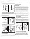
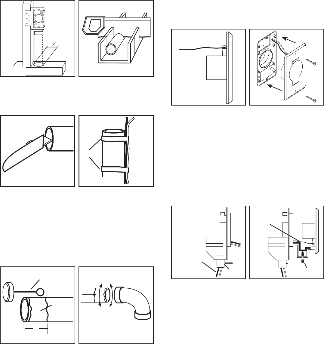
2. Connect the low voltage wire to the terminal screws on the rear of the wall
inlet (Figure 11).
3. Align the inlet screw holes with the mounting plate holes and press the inlet
into place, guiding any extra wire back through the mounting plate as you
go. Attach wall inlet to mounting plate with provided screws (Figure 12).
Installing Electric Wall Inlet Models CVIV65A or CVIV65W
CAUTION: INSTALLATION WORK AND ELECTRICAL WIRING MUST
BE DONE BY QUALIFIED PERSON(S) IN ACCORDANCE WITH ALL APPLICABLE
CODES AND STANDARDS, INCLUDING FIRE-RELATED CONSTRUCTION.
CAUTION: MAKE SURE POWER IS SWITCHED OFF AT SERVICE PANEL
BEFORE STARTING INSTALLATION.
1. Before the drywall is installed, run wire from a nearby electrical outlet box
or junction box through the supplied strain relief and into the hole in the
mounting plate, leaving about 10" of excess to make the connections to the
inlet. Secure the wire in place by tightening the strain relief (Figure 13).
2. Cap the loose wires and tuck back inside of mounting plate. Once the drywall
has been completed the wall inlets can be installed. Start by checking the
mounting plate for any debris that might have been left from the drywall
process and clean if necessary.
3. Connect the low voltage wire to the terminal screws on the rear of the wall
inlet. Second connect the black wire from the supply to the black wire of
the inlet, then connect the white wire from the supply to the white wire of
the inlet. Use approved electrical wire nuts for all connections (Figure 14).
4. Align the inlet screw holes with the mounting plate holes and press the inlet
into place, guiding any extra wire back through the mounting plate as you
go. Attach wall inlet to mounting plate with provided screws (Figure 12).
NOTE: The electrified wall inlet should be listed on the inspection report for
building inspection purposes.
Installing the Tubing
NOTE: When installing the tubing, start at the farthest inlet and work towards
the power unit. Keep the tubing as straight as possible with the least amount
of elbows and tees as possible to ensure maximum performance of your system.
When installing tees or elbows, make sure the curve in the fitting is aligned so
that the air flow is towards the power unit.
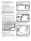
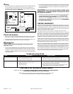
1. Cut a 2-1/2" diameter hole in the sole plate, header, or stud directly in line
with the opening of the inlet fitting (Figure 5).
2. Measure the length of tubing needed to connect into the main trunk line,
adding approximately 3/4" of tubing for insertion into fittings.
3. Cut the tubing, taking care to keep the straight square edge. The use of a
miter box is recommended (Figure 6).
4. Remove rough edges with a utility knife or coarse sand paper (Figure 7).
5. Dry fit all pieces and ensure proper fit and alignment before cementing.
6. When dry fitting tubing, run low voltage wire (minimum, solid 18 gauge, two
conductor) by securing to tubing with tape. Allow approximately 6" of excess
wire for connection to each inlet (Figure 8).
NOTE: PVC solvent cement “welds” the fitting to the tubing through a chemical
reaction to produce an air tight seal. It is important to make sure all surfaces
are clean and free of burrs to ensure a proper seal.
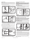
7. Once all tubing has been cut, cleaned, and checked for fit, apply model
CVFA35 PVC cement (not included) or equivalent cement to the outside of
the tubing covering about 1". DO NOT allow any of the cement to enter the
inside of the tubing (Figure 9).
8. Insert tubing with cement into fitting with a twisting motion to ensure the
cement has been evenly spread. Check that the tubing is evenly seated in
the fitting and is aligned properly with the rest of the line (Figure 10).
2-1/4"
Tape
Low
Voltage
Wire
Extra wire for inlet
connection
Cement
1"
Cement
Applicator
Strain
Relief
Supply
Wires from
Electrical Box
Wire Nut
Low
Voltage
Wire
000000 Rev A. 3-05
www.airkinglimited.com
3 of 16
Figure 5 Figure 6
Figure 7 Figure 8
Figure 9 Figure 10
Figure 11 Figure 12
Figure 13 Figure 14