


www.airkinglimited.com
AIDB4YEF New 3-07 3 of 8
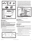
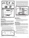
2. Bring incoming electrical service through the romex connector
and the fan knockout. Be sure to place the connector nut over the
wiring coming into the terminal box. There are three open ports
on the terminal strip. Using a small regular screwdriver, tighten
the Neutral (white) wire of the incoming supply under the open
terminal labeled "N". Tighten the Line (black) wire of the incoming
supply under the open terminal labeled "L". Tighten the Ground
(green) wire of the incoming supply under the open terminal labeled
" "
(Figure 6). For reference, a wiring diagram is included on the
inside of the terminal box lid.
3. Secure the incoming supply with the romex connector and replace
the fan terminal box cover.
4. Restore power to the unit and test the installation.
SECTION 5
Finishing the Installation
1. Included with the unit is an identifying label that must be placed
above the dryer. This label serves as a reminder that there is a
booster fan installed and that periodic cleaning must take place.
SECTION 6
Use and Care
CAUTION: MAKE SURE POWER IS SWITCHED OFF AT SERVICE
PANEL BEFORE SERVICING THE UNIT.
1.
Fan impeller may accumulate lint. Periodic inspection, based upon
dryer usage, should be performed to ensure that the fan impeller
is not obstructed or loaded with lint. Under normal conditions, fan
should be inspected a minimum of every Six (6) Months.To inspect
and clean the impeller:
a. Disconnect the incoming power supply at the source.
b. Remove the duct from the fan inlet and remove any lint buildup
on the impeller.
c. Reconnect the duct to the fan. Turn power supply on.
NOTE: Excessive booster fan noise or vibration may be an indication
of lint buildup on the impeller.
2. The fan’s bearings are sealed and provided with an internal
lubricating material, no additional lubrication is necessary.
NOTE: Steps 2 and 3 may be reversed.
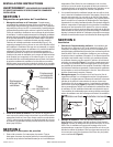
SECTION 4
Electrical Connections
CAUTION: MAKE SURE POWER IS SWITCHED OFF AT SERVICE
PANEL BEFORE STARTING INSTALLATION.
CAUTION: ALL ELECTRICAL CONNECTIONS MUST BE MADE
IN ACCORDANCE WITH LOCAL CODES, ORDINANCES, OR NATIONAL
ELECTRICAL CODE. IF YOU ARE UNFAMILIAR WITH METHODS OF
INSTALLING ELECTRICAL WIRING, SECURE THE SERVICES OF A
QUALIFIED ELECTRICIAN.
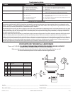
NOTE: The fan motor, capacitor and pressure switch connections are
pre-wired from the factory.
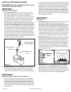
1. Remove the screws securing the terminal box cover plate located
on the side of the fan. All fan motor connections are prewired to
an electrical terminal strip. A 3|8" romex type cable restraint
connector will be needed to secure the wiring through the knockout
provided on the side of the terminal box (Figure 5).
Bracket
Stud
Figure 4
Fan
Screws
Figure 3
Correct Positions
Incorrect Positions
Figure 5
Screws
Terminal Box
Supply from house
Green
Black
Ground
White
N
L
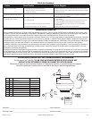
Figure 6
Black
White
Red
Brown
Blue
Black
Capacitor