


INSTALLATION INSTRUCTIONS
CAUTION:
MAKE SURE POWER IS SWITCHED OFF AT SERVICE
PANEL BEFORE STARTING INSTALLATION.
SECTION 1
Preparing for Installation
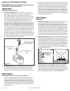
1. Fan and Switch Mounting: The recommended location of the
booster fan is a minimum of 15 linear (not equivalent) feet of duct
from the dryer outlet. If the fan is mounted closer than the
recommended 15 feet, it may develop enough pressure to lift wet
lint into the fan impeller resulting in excessive lint loading in the
fan. The best location for the fan to be mounted is as close as
possible to the termination of the duct work. (Exception: If a
secondary lint filter is installed between the dryer and the booster
fan, the booster fan may be mounted within the minimum distance
otherwise recommended (Figure 1). A mounting bracket attached
to a rafter or joist should be used to stabilize the fan. Although not
recommended, a vertical rigid duct may support the fan if the duct
is securely stabilized. (Consult local codes prior to supporting the
fan in the duct alone.) Duct work should be attached to the inlet
and outlet of the fan by means of vibration isolation clamps (not
included) or ducting tape. The duct connection should be properly
sealed to prevent leakage and loss of fan performance. Flex duct
connections between the dryer duct connection and exhaust duct
should be stretched as smooth as possible.
2. Calculating Duct Run: To calculate the length of your planned duct
run, measure from the dryer to external venting point in roof or
wall. For each bend or elbow add 5-7 feet to your total duct run
calculations. This booster fan can be used on runs up to 108 feet.
SECTION 2
Understanding the Pressure Sensor Switch
1. This unit is equipped with a pressure switch. This is a positive
pressure sensing switch which recognizes dryer operation and
activates the booster fan from an independent electrical circuit.
This eliminates connections through the dryer circuit which may
void the manufacturers’ warranty as well as manual systems which
require the attention of the operator or costly current/temperature
sensing systems.
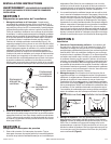
2. The electricity to the booster fan is connected in series through a
normally open terminal on the switch. A pressure tap is connected
to a fitting on the side of the switch. When the dryer begins operation,
positive pressure in the duct causes the switch diaphragm to
expand, closing the circuit to the booster fan. An integral delay-
on-break timer in the switch will cycle the fan on for intervals of
10 minutes. This will continue until the dryer has stopped and the
timer delay period has lapsed. Drying cycles, the booster fan, the
delay timer and the pressure switch are not adversely affected by
the starting/stopping intervals.
SECTION 3
Installation
1. Selecting Fan Location: Fan must be mounted a minimum of 15 feet
from the dryer outlet. If the fan is mounted closer than the
recommended 15 feet, it may develop enough pressure to lift wet
lint into the fan impeller resulting in excessive lint loading in the
fan. (Exception: If a secondary lint filter is installed between the
dryer and the booster fan, the booster fan may be mounted within
the minimum distance otherwise recommended (Figure 1). The best
location for the fan to be mounted, in any application, is as close
as possible to the termination of the duct work. In order to perform
recommended maintenance, fan location should allow sufficient
access for service. Refer to dimensional drawings shown above.
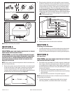
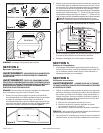
2. Mounting the Bracket: Using the wood screws provided, attach the
mounting bracket to a support beam at the selected location. Bracket
is provided with grommets in order to isolate any vibration and
prevent the transmission of sound through the structure. Be careful
not to overtighten. Fan mounting can be in any angle (Figure 2),
however, vertical mounting is recommended to reduce condensation
buildup in the fan. If a horizontal installation is necessary and
condensation buildup may pose a problem, wrap insulation around
the fan to minimize buildup.
3. Mounting the Fan: For proper operation, the switch diaphragm
must be positioned vertically (Figure 3). Wiring box should be
positioned for easy access. Attach fan to the mounting bracket
with the self tapping screws provided. Care should be taken not to
strip the plastic housing. Although screw pilot holes are not required,
3|32" (or smaller) pilot holes are recommended (Figure 4).
www.airkinglimited.com
AIDB4YEF New 3-07 2 of 8
Figure 1
Secondary Lint
Trap
Figure 2
or
Vertical Mounting
Bracket
Stud
Bracket
Joist
Horizontal Mounting
Recommended
Fan Location
Alternative Fan
Location