


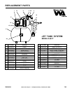

23833A343
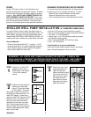
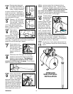
STEP
4
Remove pipe clamp and
slide Well Seal #RWS4-12
over PVC pipe and onto well
casing. Position assembly
so twelve inches of PVC pipe pro-
trude from well seal. Alternately turn
bolts on well seal counterclockwise
until rubber gaskets are tight against
well casing and PVC pipe.
APPROX.
12" OF
PVC PIPE
PROTRUDING
FROM WELL
SEAL
WELL
SEAL
#RWS4-12
of PVC pipe before cementing
elbow. Smooth inside of any cut
PVC pipe with file or knife.
STEP
5
Cement 1-1/4" PVC elbow
onto PVC pipe protruding
from well seal. If desired,
some length may be cut off
1-1/4"
PVC
ELBOW
TOP OF
PVC PIPE
PROTRUDING
FROM WELL
SEAL
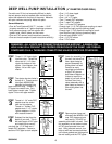
STEP
9
Place a large bucket
beneath the pressure
regulator outlet. Start
motor. Turn regulator
(part #25881A281 stamped on the side) into larger hole
until snug. Put gasket over venturi tube so openings in
gasket line up with openings in ejector.
STEP
6
Open ejector
pack included
with your jet sys-
tem. The ejector
has two holes in its top.
Thread the venturi tube
GASKET
VENTURI
TUBE
EJECTOR
BOLTS
STEP
7
Secure ejector and
gasket to front of tank-
mounted pump with
bolts provided. Thread
a 1-1/14" male PVC
adapter into front of
ejector.
Cement as much PVC pipe and couplings
needed to connect PVC elbow to male PVC
adapter in front of ejector. The diaphragm
pressure tank is preset to 30 PSI. Reset
STEP
8
pressure to 18 PSI using a tire gauge. This is vital to
proper operation of the system.
MALE PVC
ADAPTER
EJECTOR
PRESSURE
GAUGE
ADJUSTMENT
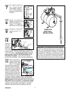
5
PRESSURE
REGULATOR
adjustment screw down tight.
If pump is properly primed a
high pressure will immediately
show on the pressure gauge.
With pump operating at high
pressure, slowly unscrew reg-
ulator adjustment screw until
maximum water flow is obtained without
pressure dropping to zero. If pressure falls
completely, retighten adjustment screw and
read-just. Steady pressure must not be less
than 24 lbs. for the R520. If no pressure shows:
Stop motor, remove pressure gauge plug from pressure
regulator, add more water, and try again.
STEP
10
Thread pressure
gauge plug back
into discharge
tee. Thread
pressure gauge into pres-
sure gauge plug. Make
sure all connections are
tightly sealed. Place a
large basin beneath dia-
phragm tank outlet. Start
motor. If pump is off-set
from well 4 feet or more, it
may take a few minutes
for pump to prime. Failure to prime in 5 minutes:
Stop motor, remove pressure gauge plug from dis-
charge tee, add more water, try again. Allow pump to
run long enough to clear the well of sand or dirt and to
insure well will not run dry. Stop motor.
STEP 9
CONT'D
Connect the 1" tank outlet to the service line.
Total installation should look like the drawing
below.
STEP
11
COMPLETE
SHALLOW WELL
INSTALLATION