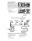
The water pressure in
the tank will increase as
the tank fills with water.
When the pressure in the
tank reaches approxi-
mately 80 psi (552 kPa)
the filter system shuts off.
When water is drawn from
the tank and the pressure
drops to approximately 60
psi (414 kPa), the filter
system will automatical-
ly turn on.
If the tank pressure drops
to 40 psi (276 kPa) the
auto-bypass solenoid valve
will open allowing unfiltered
water to flow to service
until tank pressure reaches
approximately 60 psi (414
kPa). When the filter sys-
tem is in auto-bypass the
red light on the front of
the bracket will come on.
NOTE: TSR150-2/2A/2B
Bypass at 20psi (138
kPa) to 40 psi (276 kPa).
IMPORTANT!
The use of metallic piping
materials for high quality
water is not recommend-
ed because the water is
aggressive due to low TDS
and pH. Plastic tubing and
pipe are most suitable.
Solvent bonded plastic pipe
should be assembled care-
fully to avoid excessive glue
inside the pipe. Piping of
any type should be flushed
thoroughly before use. Be
sure piping conforms to
local plumbing codes.
Drain Connection
Important: An approved air gap should exist between the filter system
drain lines and the drain opening to meet local plumbing codes.
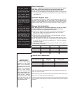
1. Run a minimum 3/8” O.D. tube from the reject port to the drain.
2. The 3/8” O.D. reject tubing line may be run up to 10 ft (3 m) from the
filter system to the drain. Care must be taken not to crimp or block the
reject tubing line.
Automatic Bypass Valve
The auto-bypass valve has 3/8” MNPT inlet and outlet ports and a 6’ (183
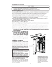
cm) power cord that plugs into the filter system. This auto-bypass valve
should be installed between the incoming unfiltered water line to the filter
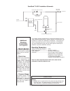
system and the water line to service after check valve. (Refer to page 4.)
Storage Tank Installation
Note: Storage tanks are purchased separately. Consult the CUNO
®
Foodservice Price List for applicable sizes and part numbers.
1. Follow installation instructions provided with tank.
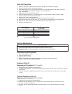
2. Check the air pressure in the tank at the valve in the top of the tank.
With the tank empty, the pressure should be 20 psi (137.9 kPa).
Adjust the air pressure as required.
3. Place the tank in the desired location. It should be placed in an area
where it will not be bumped or jarred.
4. Connect fitting and minimum 3/8” O.D. tubing to product port of the unit.
5. Run tubing from the other side of the TEE to the check valve and
on to point of use connection and bypass line. Refer to Installation
Schematic on page 4.
6. Open the ball valve on the tank by turning the handle until it is parallel
with the body of the valve.
Point-of-Use Connections
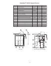
Storage Tank Diameter Height Pipe Connection
2.5 gal. (9.5 lit.) 9 1/16" (23 cm) 14 1/8" (35.9 cm) 1/4" (0.6 cm)
5 gal. (19 lit.) 15 3/8" (39.1 cm) 17 3/8" (44.1 cm) 3/4" (1.9 cm)
10 gal. (38 lit.) 16" (40.6 cm) 32 1/2" (82.6 cm) 1" (2.5 cm)
20 gal. (76 lit.) 16" (40.6 cm) 57 1/2" (146.1 cm) 1" (2.5 cm)
40 gal. (151 lit.) 24" (61 cm) 56 1/2" (143.5 cm) 1 1/4" (3.2 cm)
Distance from Storage
Tank to Point of Use
Recommended Minimum
Tubing Size
Recommended Minimum
Plastic Pipe Size
up to 5 ft (0-1.5 m) 1/2" O.D. (1.3 cm) 3/8" (1 cm) Schedule 40 PVC
5-20 ft (1.5-6.1 m) 3/4" O.D. (1.9 cm) 1/2" (1.3 cm) Schedule 40 PVC
20-40 ft. (6.1-12.2 m) N/R 1/2" (1.3 cm) Schedule 40 PVC
40-60 ft. (12.2-18.3 m) N/R 3/4" (1.9 cm) Schedule 40 PVC
Note: The above table is appropriate for point of use applications that require flow
rates up to 5 gpm (18.9 lpm).
Select the tubing or pipe size that will help provide adequate flow and pressure to the
point of use (i.e. Longer runs require larger tubing).
The type of tubing or pipe used must conform to local plumbing codes. Tubing or pipe
used for drinking water applications must be NSF listed or made of FDA compliant
materials.
6


