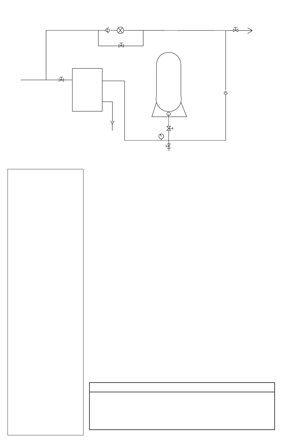
m e t s y S O R
0 5 1 M T S
s u l P v e B
s m e t s y S R S T
y l p p
u S
retaW
ec i v r e S o T
k n a T O R
e v l a V k c e h C
k n a T l a u n a M
e v l a V
e n i L r e t a W
O R " 8 / 3
. y s s A e v l a
V d i o n e l o S s s a p y B
n i a r D
n/Sample ValveiarD knaT
s s a p y B l a u n a M
) l a n o i t p O (
telnI
e v l a V
Service Shut
Off Valve
(Optional)
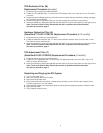
If your water analysis indicates that any of these parameters are not in
range, additional pretreatment or higher frequency of maintenance may
be required. Contact your distributor for assistance. The presence of
silica or flocculants (e.g. alum or cationic polymers) in the feedwater
can cause membrane fouling and may require special chemical pre-
treatment or periodic membrane cleaning.
Operating Parameters:
Typical TDS Cartridge Rejection ..... >95%
Feed Temperature ...........................40-100°F (4-38°C)
Feed Pressure ................................. 20-65 psi (138-448 kPa)*
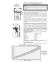
Production .......................................... Chart on page 3 shows output in
gallons per hour at varying water
temperatures. Actual output may
vary according to feedwater
conditions and membrane variations.
Note: For water temperature below 50°F (10°C) water can be
preheated to improve production rate.
*To reduce the risk associated with property damage due to water
leakage:
• Do not install on systems where line pressures above 65 psi (448
kPa) may occur. Line water pressure in excess of 65 psi will re-
quire installation of a pressure regulator prior to the unit.
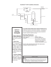
Additional
Plumbing
Connections
(not supplied)
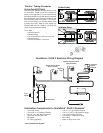
• Manual Bypass:
A manual bypass loop is
recommended to facilitate
proper service of the filter
system.
• Drain Line:
A drain line is recommend-
ed to depressurize the
system during cartridge
changeout, for sanitizing
the system, and for drain-
ing the tank. Note: 10, 20,
and 40 gallon (38, 76, 151
liter) tanks are capable of
draining water in excess
of 13 gpm (49 lpm). Drain
connection must be sized
accordingly.
• Pressure Gauge:
A pressure gauge in the
product water line is rec-
ommended to determine
the system’s performance
and when the system is
de-pressurized.
ScaleGard
™
PLUS 2 Installation Schematic
4
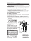
CAUTION


