2
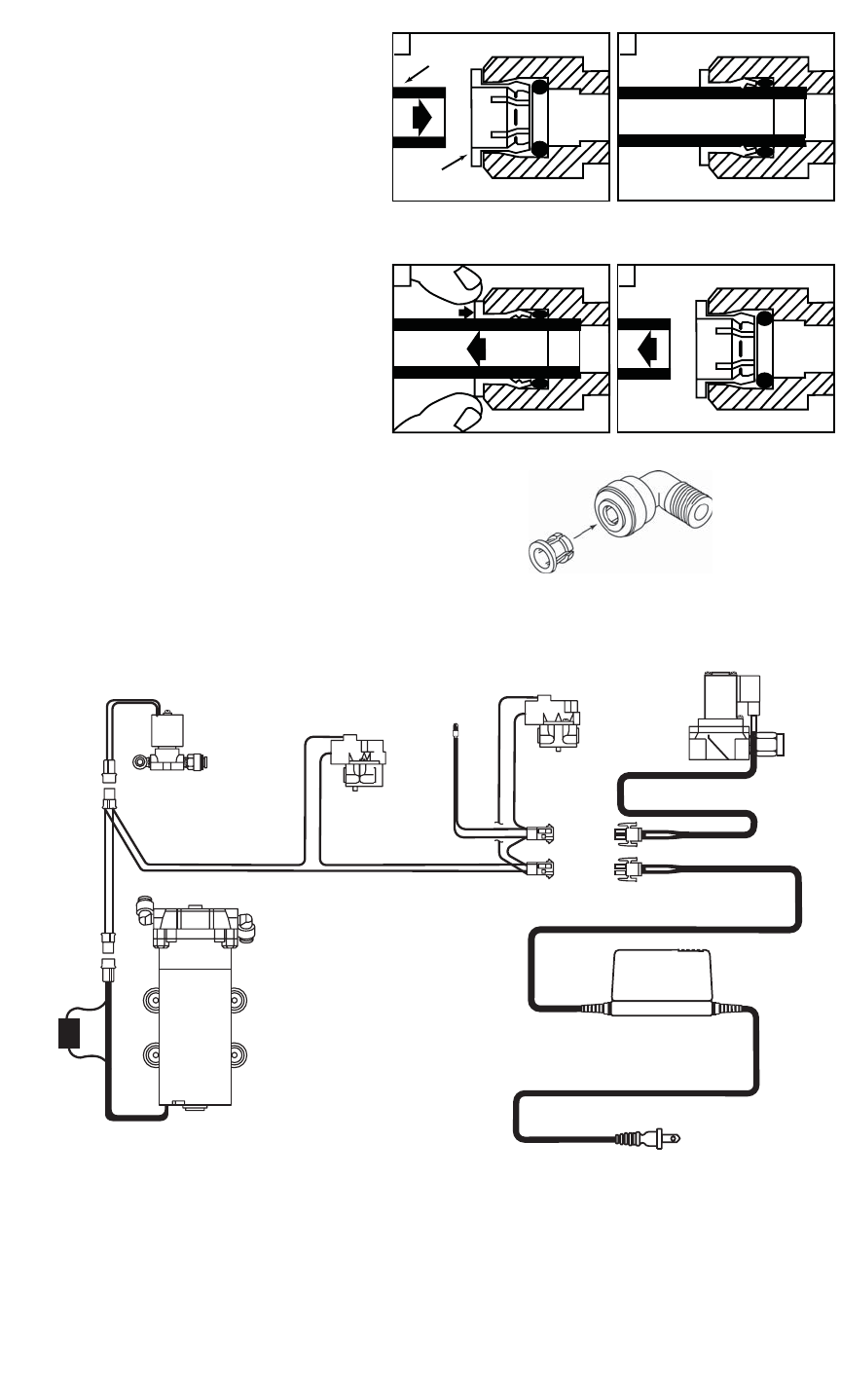
Tubing is secured in.
Grey Collet
Tube
Push tubing straight in as far as it will go.
1
Pull tubing straight out.
2
To Attach Tubing
1
Push in grey collet to release tubing.
To Release Tubing
‘Push-In’ Tubing Connector
(John Guest® Fitting)
This product is outfitted with user friendly “Push
In” connectors. Proper use of the connectors is
shown in the diagrams. It is most important that
the tubing selected for use with these connectors
be of high quality, exact size and roundness, and
with no surface nicks or scratches. If it is neces-
sary to cut the tubing, use a plastic tubing cutter
or sharp razor knife. Make a clean square cut.
Should a leak occur at a ‘Push In’ connector, the
cause is usually defective tubing.
To fix leaks:
• Relieve pressure.
• Release tubing.
• Cut off at least 3/8” (9.5 mm) from end.
• Reattach tubing.
• Confirm connection is leak free.
Installation Components for ScaleGard
™
PLUS 2 Systems*
• 1 pc of 3/8” Cross • 1 pc of 1/4” x 3/8” Male Connector
• 1 pc of 3/8” x 1/4” Reducer Bushing • 1 pc of 1/4” NPT 0-160 pressure gauge
• 6 pcs of 1/2” x 3/8” Male Connector • 1 pc of 3/8” Female Pipe Tee
• 1 pc of 3/8” Female Ball Valve • 1 pc of 3/8”x1” Reducer Bushing
• 3/8” Nipple • 3/8” Tubing
• 1/2” Tubing (optional) • Cutter or sharp razor knife.
* Not Provided With System
Solenoid
Tank Pressure Switch
(Blue Terminal)
Bypass Pressure Switch
(Red Terminals)
Bypass
Light
Booster Pump
Transformer
Automatic
Bypass
Solenoid
ScaleGard
™
PLUS 2 Electrical Wiring Diagram
9
Fuse
Holder


