


Step 7) Attach DRAIN LINE to DRAIN LINE FITTING. To prevent back pressure from reducing fl ow
rate below minimum required for backwash, DRAIN LINE MUST be sized according to run
length and relative height. Be careful not to bend fl exible drain tubing sharply enough to
cause “kinking” (if kinking occurs DRAIN LINE MUST BE REPLACED). Typical examples of
proper DRAIN LINE diameters are:
1) 1/2” ID up to 15 ft. when discharge is lower than INLET.
2) 5/8” ID up to 15 ft. when discharge is slightly higher than the INLET.
3) 3/4” ID when drain is 25 ft. away and/or drain is installed overhead.
Some areas prohibit the use of fl exible drain lines. Check with local code offi cials prior to
installation.
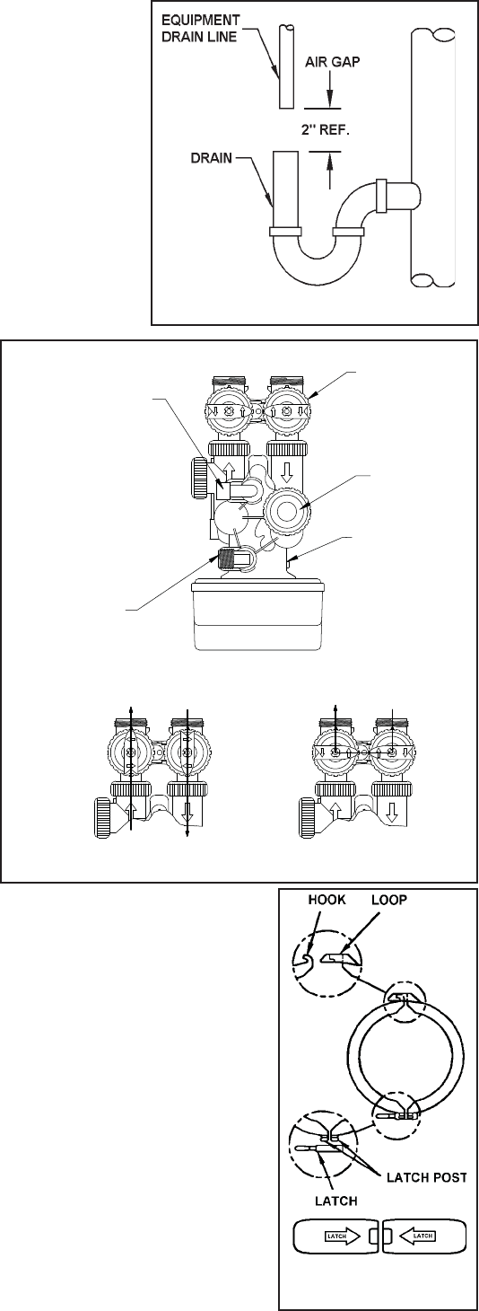
Step 8) Position DRAIN LINE over drain and secure fi rmly. To prevent backsiphoning of sewer
water, provide an air-gap of at least 2” or 2 pipe diameters between end of drain hose and
drain (Figure 3). DO NOT raise DRAIN LINE more than 10 ft. above fl oor.
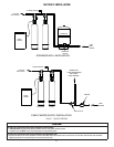
Step 9) Connect one end of the 3/8” black Polyethylene tubing to the brine
fi tting located on the left side of the CONTROL VALVE. Connect the
other end to the SAFETY BRINE VALVE ELBOW inside of the brine
well in the brine tank. To do so remove the retaining clip from the
brine line fi tting on the control valve. The retaining clip is holding
a plastic insert sleeve and needs to be inserted into the polyeth-
ylene tubing before installing the tubing into the fi tting elbow and
hand tighten only. CAUTION: Do not use pliers or wrenches to
tighten as damage may occur and will void the manufacturer’s
warranty.
Step 10) Install OVERFLOW LINE to brine tank OVERFLOW FITTING (Figure 2).
Discharge of line must be lower than OVERFLOW FITTING. DO NOT
INTERCONNECT OVERFLOW LINE WITH VALVE DRAIN LINE.
Step 11) Make certain BYPASS VALVE INLET and OUTLET KNOBS ARE IN
“BYPASS” position. After all plumbing connections have been
completed, open main water shut-off valve or restore power to
well pump. Check for leaks and correct as necessary.
Step 12)Plug CONTROL VALVE POWER CORD into 120v/60Hz, non-switched power
source. Manually stage control to BACKWASH POSITION and then
unplug power cord to prevent the unit from advancing automati-
cally.
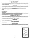
Step 13) Partially open INLET knob on bypass valve (Figure 4). This will
allow the unit to fi ll slowly from the bottom up, reducing air en-
trapment. Allow unit to fi ll slowly, failure to do so could result in
loss of resin to the drain. Once a steady stream of water, no air,
is fl owing to drain the inlet and outlet knobs on the bypass can be
fully opened.
Step 14) Plug the power cord back into the power source. Press the REGEN button and wait for the valve to advance to the
next regeneration position. Repeat the process until the valve is in Service Position (Time will be on the display).
Step 15) Refer to Section 3: Regeneration Instructions, on how to set control valve for proper set up and regeneration
settings.
NOTE: Regeneration settings for the control valve are factory preset. The control valve design permits adjustment
of the salt setting. This adjustment may be necessary when unusual operating conditions exist, such as high
concentrations of iron, manganese or hardness and/or high fl ow rates or daily water consumption.
SPECIAL SERVICE INSTRUCTIONS:
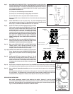
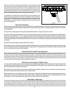
Under normal circumstances removal of valve should not be required. However, if it must be removed, it
can be done by disassembling the quick release clamp, and latch. Pressure should be relieved before attempting any
disassembly. Upon reassembly, all o-rings should be lubricated with silicone grease. Reassemble clamp as shown in
Figure 5. MAKE SURE ARROWS ON LATCH SIDE OF CLAMP ARE ALIGNED.
2-3
Figure 3
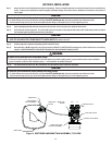
Figure 4. BYPASS VALVE
BYPASS VALVE
INOUT
CONTROL VALVE BODY
DRAIN LINE FLOW
CONTROL ASSEMBLY
BRINE LINE
ELBOW
INJECTOR COVER
OFF
OFF
OFF
OFF
OFF
OFF
OFF
OFF
OFF
OFF
OFF
OFF
Supply Water
Enters
Supply (Untreated)
Water Exits
Supply Water
Enters
Treated Water
Exits
NORMAL OPERATION BYPASS OPERATION
Figure 5.
Clamp Assembly