5-4
the left side of the control valve. Pliers may be used to unscrew the nut if necessary. With the nut removed, a slot at the top of the water meter is visible. Twist a fl at
blade screwdriver in the slot between the control valve body and the meter. When the meter is part way out it is easy to remove the water meter from the housing.
Once the water meter is removed from the control valve body, gently pull forward on the turbine to remove it from the shaft.
Do not use a wire brush to clean the turbine. Wipe with a clean cloth or clean in dilute sodium bisulfi te or vinegar. The turbine can be immersed in the chemical. Do
not immerse electronics. If the turbine is scored or damaged or the bearing on the turbine are worn, replace the turbine.
Do not lubricate the turbine shaft. The turbine shaft bearings are prelubricated. Do not use petroleum jellies, oils, or other unacceptable lubricants on the o-ring. A
silicone lubricant may be used on the black o-ring.
Snap the turbine on the shaft and reinsert the water meter into the side slot. Hand tighten the nut. Do not use a pipe wrench to tighten nut.
Bypass Valve:
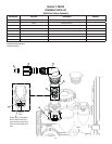
The working parts of the bypass valve are the rotor assemblies that are contained under the bypass valve caps. Before working on the rotors, make sure the system
is depressurized. Turn the red arrow shaped handles towards the center of the bypass valve and back several times to ensure rotor is turning freely.
The nuts and caps are designed to be unscrewed or tightened by hand. If necessary a pliers can be used to unscrew the nut or cap. Do not use a pipe wrench to
tighten or loosen nuts or caps. Do not place screwdriver in slots on caps and/or tap with a hammer. To access the rotor, unscrew the cap and lift the cap, rotor and
handle out as one unit. Twisting the unit as you pull it out will help to remove it more easily. There are three o-rings: one under the rotor cap, one on the rotor stem
and the rotor seal. Replace worn o-rings. Clean rotor. Reinstall rotor.
When reinstalling the red arrow handles be sure that:
1. The handle pointers are lined up with the control valve body arrows, and the rotor seal o-ring and the retainer on both rotors face to the right when being
viewed from the front of the control valve; or
2. Arrows point toward each other in the bypass position.
Since the handles can be pulled off, they could be accidentally reinstalled 180° from their correct orientation. To install the red arrow handles correctly, keep the
handles pointed in the same direction as the arrows engraved on the control valve body while tightening the bypass valve caps. After completing and valve mainte-
nance, press and hold NEXT and REGEN buttons for 3 seconds or unplug power source jack (black wire) and plug back in. The resets the electronics and establishes
the service piston position. The display should fl ash all wording, then fl ash the software version (e.g. 181) and then reset the valve to the service position.


