


78-8117-0985-2 Rev C 13
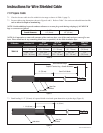
Instructions for UniShield® Shielded Cable
12.0 Prepare Cable
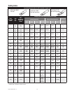
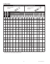
12.1 Check to be sure cable size fits within kit size range as shown in Table 1 (page 2).
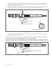
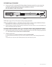
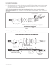
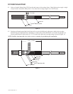
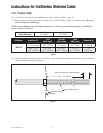
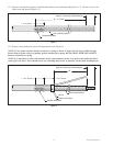
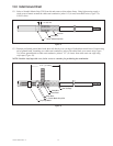
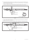
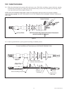
12.2 Prepare cable using dimensions shown in Figure 16, 17 and 18. Refer to Table 4 for dimension [A]. Be sure to
allow for depth of terminal lug.
NOTE: Provide additional exposed conductor distance to account for growth during crimping of ALUMINUM
lugs or connectors as follows:
Aluminum Connector
Growth Allowance
2 - 350
1/4” (6 mm)
400 - 650
1/2" (13 mm)
Kit Number Insulation 0.D.
15 kV
AWG / kcmil
25/28 kV
AWG / kcmil
35 kV
AWG / kcmil
Dimension [A]
7684-S-8
0.83" - 1.21"
(21,1 - 30,7 mm)
4/0 - 300
(120 - 150 mm
2
)
2/0-3/0
(70 - 95 mm
2
)
2 - 2/0
(35 - 70 mm
2
)
13.5"
(342,9 mm)
0.98" - 1.53"
(24,9 - 38,9 mm)
350 - 500
(185 - 240 mm
2
)
4/0 - 250
(120 - 150 mm
2
)
3/0 - 4/0
(95 - 120 mm
2
)
13.0"
(330,2 mm)
Table 4
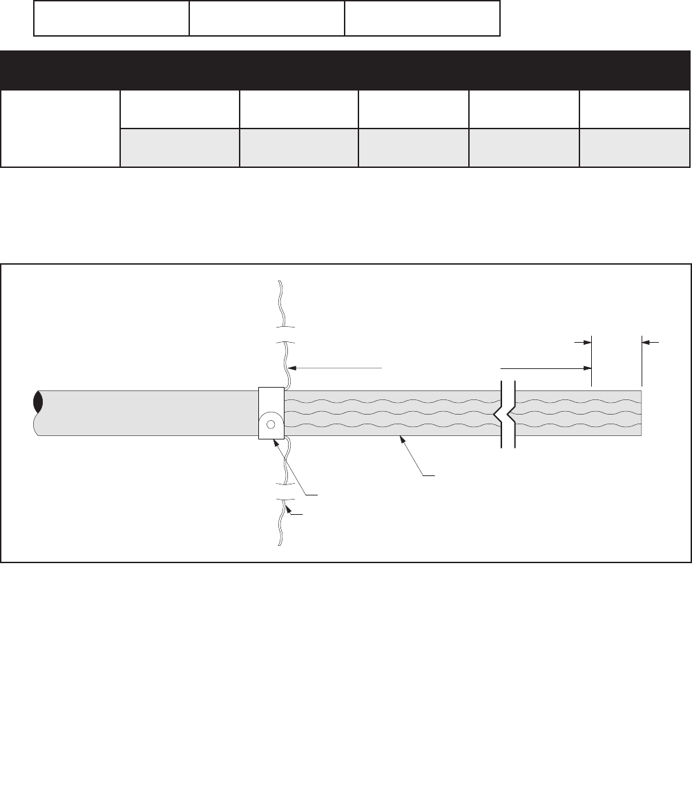
12.3 Install constant force spring as shown in Figure 16. Pull shield wires through semi-conductive jacket to leading
edge of constant force spring (Figure 16).
[A] + 1 1/2” (38 mm)
Semi-Conductive Jacket
Constant Force Spring
Shield Wires
Depth Of T
erminal Lug + Growth Allowance
Figure 16