


78-8113-5099-6 Rev E 11
11.2 Connect ground braid to system ground according to standard practice.
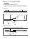
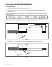
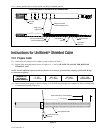
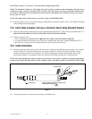
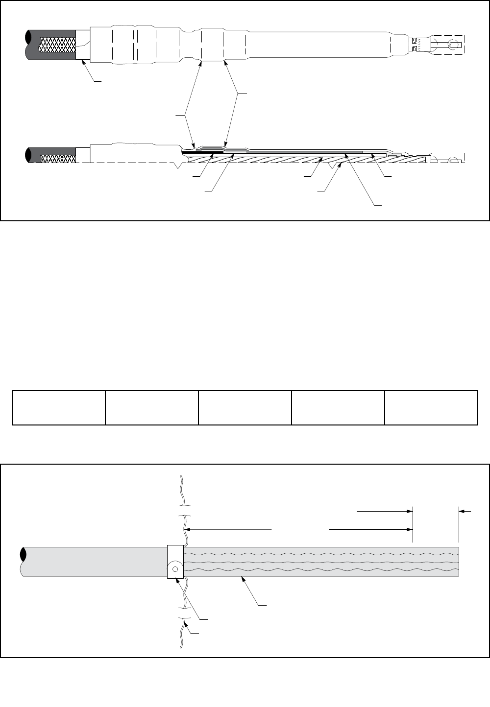
Semi-Con Insulation Shield
Ridge at End of Cable
Insulation Shield (Semi-Con)
Ridge at End
of High-K Tube
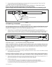
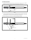
Correct Installation of Termination on Wire Shielded Cable
Cable Insulation
Conductor
Vinyl Tape
Marker
Seal
Stress Controlling Compound
High-K Stress
Relief Tube
Environmental Top
Instructions for UniShield
®
Shielded Cable
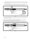
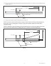
12.0 Prepare Cable
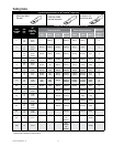
12.1 Check to be sure cable size fits within kit range as shown in Table 1.
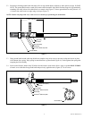
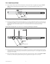
12.2 Prepare cable using dimensions shown in Figures 16, 17 and 18. BE SURE TO ALLOW FOR DEPTH OF
TERMINAL LUG.
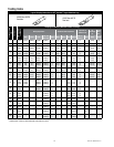
NOTE: Provide additional exposed conductor distance to account for growth during crimping of ALUMINUM lugs
or connectors as follows:
Aluminum Lug
and Connector
Growth Allowance
2 - 350
1/4” (6 mm)
400 - 650
1/2” (13 mm)
750–1000
3/4” (19 mm)
1250 - 2000
Field determined
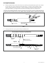
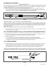
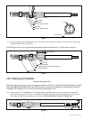
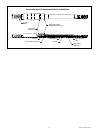
12.3 Install constant force spring as shown in Figure 16. Pull shield wires through semi-conductive jacket to leading edge
of constant force spring (Figure 16).
Depth Of Terminal Lug + Growth Allowance
7-1/2" (191 mm)
Semi-Conductive Jacket
Constant Force Spring
Shield Wires
Figure 16