


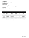
10 78-8113-5099-6 Rev E
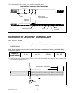
9.0 Install Lug or Connector
Important Packaging Notice
In order to make sure that you receive an undamaged termination, this 3M™ Cold Shrink QT-III Termination is packed
with a RED SHIPPING CORE inside of the white core. Please remove the red shipping core BEFORE you install the
termination. This shipping core can be recycled with other polypropylene waste
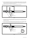
9.1 Check to insure 3M
™
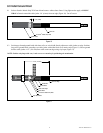
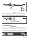
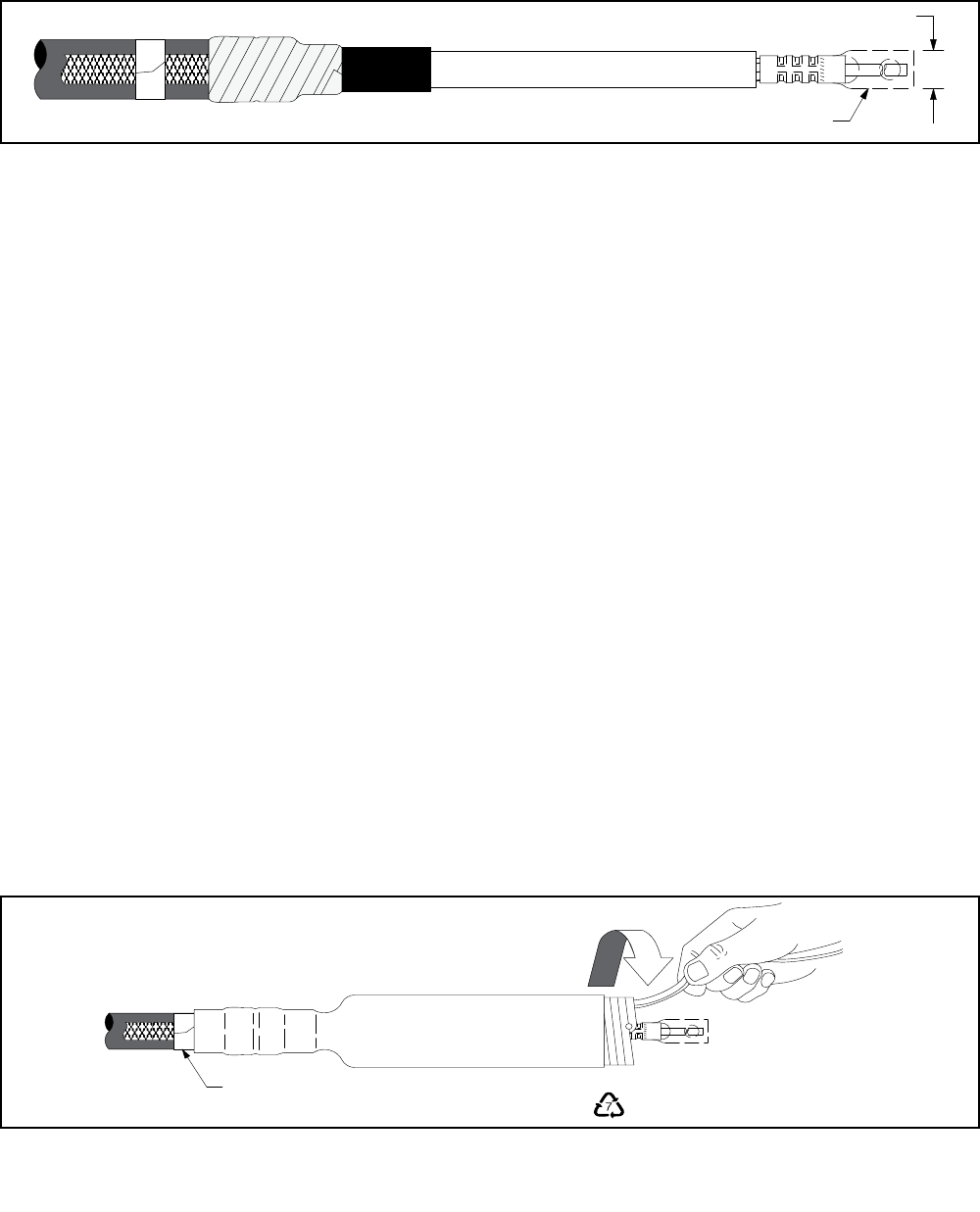
Cold Shrink QT-III Silicone Rubber Termination fits over the selected lug or connector. If
lug or connector (Figure 14) will not fit through the termination core, clean the insulation (per Step 10.0) and slide
termination on cable before installing lug. DO NOT REMOVE CORE AT THIS TIME.
Clearance
Connector/Lug
Figure 14
NOTE: Refer to pages 17-19 for 3M Connector and Lug crimping information.
NOTE: For Aluminum Conductors - Thoroughly wire brush conductor strands to remove aluminum oxide layer. Insert
conductor into lug or connector and then remove conductor. This will transfer some of the antioxidant compound onto
the conductor. Wire brush the anti-oxidant paste into the strands. Immediately insert conductor into lug or connector
barrel as far as it will go.
NOTE: Die/crimper head rotation between consecutive crimps is RECOMMENDED.
9.2 Position connector or lug and crimp according to manufacturer's directions. Remove excess oxide inhibitor and sharp
crimp flashings following crimping.
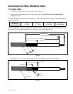
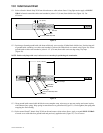
10.0 Clean Cable Insulation and Lug or Connector Barrel Using Standard Practice
10.1 Wipe the cable insulation with one of the solvent saturated pads from the 3M
™
Cable Cleaning Preparation Kit CC-2.
DO NOT ALLOW SOLVENT TO TOUCH SEMI-CON INSULATION SHIELD!
10.2 If abrasive must be used:
a. Use on insulation only. DO NOT USE ABRASIVE ON SEMI-CON INSULATION SHIELD!
b. Use only aluminum oxide abrasive; grit 120 or finer, included in the 3M Cable Cleaning Preparation Kit CC-2.
c. Be careful not to reduce the cable insulation diameter below that allowed by the kit.
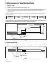
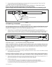
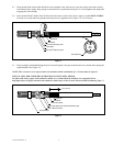
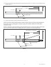
11.0 Install Termination
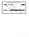
11.1 Slide the termination body onto the cable and remove core. Make sure the termination body (not the core) is butted
up to the edge of the vinyl tape marker previously applied (Figure 15). Pull the core while unwinding, counter-
clockwise, starting with the loose end (Figure 15). Be sure to alternate the pulling and unwinding actions (pull-
unwind-pull-unwind-etc.) to help prevent the core material from binding up as the core is being removed.
NOTE: Once the termination body makes contact over the mastic seal area, there is no need to continue supporting the
assembly. DO NOT PUSH OR PULL ON THE TERMINATION ASSEMBLY WHILE UNWINDING THE CORE.
Vinyl Tape Marker
Counterclockwise
NOTE: The material being removed at this step is mixed
polymers and can be recycled.
Figure 15