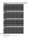
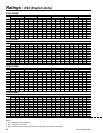
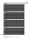
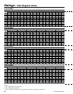
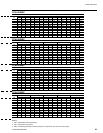
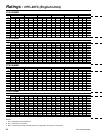
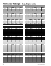
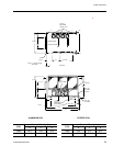
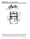
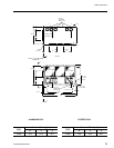
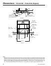
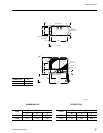
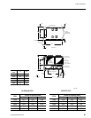
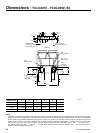
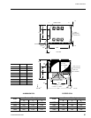
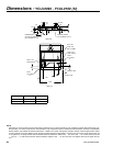
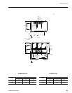
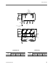
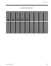
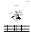
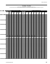
YORK INTERNATIONAL
118
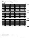
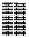
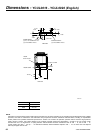
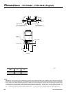
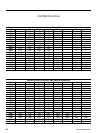
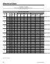
YORK INTERNATIONAL
119
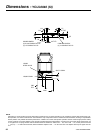
FORM 150.63-EG1
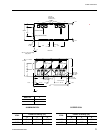
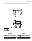
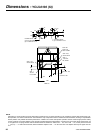
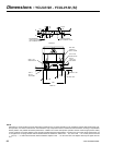
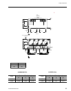
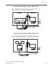
2.03 REFRIGERANT CIRCUIT
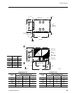
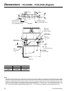
One (YCUL0016-0040) or two (YCUL0046-0130) inde-
pendent refrigerant circuits will be furnished on each
unit. All unit piping will be copper, with brazed joints. The
liquid line will include a eld connection shutoff valve with
charging port located on each condenser circuit. Suc-
tion line connections are provided on each refrigeration
circuit. Filter drier and sight glass are shipped loose for
eld installation on each refrigerant circuit.
All expansion valves and liquid line solenoid valves and
refrigerant eld piping are supplied by others.
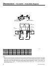
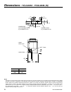
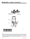
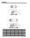
2.04 HEAT EXCHANGERS
A. Air Cooled Condenser:
1. Coils: Internally enhanced, seamless copper
tubes, mechanically expanded into aluminum
alloy ns with full height collars. Subcooling coil
an integral part of condenser. Design working
pressure shall be 450 psig (31 bar).
2. Fans: Shall be dynamically and statically
balanced, direct drive, corrosion resistant glass
ber reinforced composite blades molded into
low noise, full airfoil cross section, providing
vertical air discharge from extended orices
for efciency and low sound. Each fan in its own
compartment to prevent cross ow during fan
cycling. Guards of heavy gauge, PVC (polyvinyl
chloride) coated or galvanized steel.
3. Fan Motors: High efficiency, direct drive, 6
pole, 3 phase, insulation class “F”, current
protected, Totally Enclosed Air-Over (TEAO),
rigid mounted, with double sealed, permanently
lubricated, ball bearings.
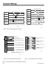
2.05 CONTROLS
A. General: Automatic start, stop, operating, and
protection sequences across the range of scheduled
conditions and transients.
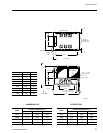
B. Microprocessor Enclosure: Rain and dust tight
NEMA 3R/12 (IP55) powder painted steel cabinet
with hinged, latched, and gasket sealed door.
C. Microprocessor Control Center:
1. Condensing Unit control can be set for Dis-
charge Air Temperature Control or for Suction
Pressure Control. (Note: Suction Pressure
Control requires optional Suction Pressure
Transducers on Models YCUL0016-0066.)
2. Automatic control of compressor start/stop,
anti-coincidence and anti-recycle timers,
automatic pump-down shut-down, condenser
fans, unit alarm contacts, and condensing unit
operation from 0°F to 125°F (-18°C to 52°C)
ambient. Automatic reset to normal chiller
operation after power failure.
3. Discharge air temperature reset via a Pulse
Width Modulated (PWM) input signal or up to
two steps of demand (load) limiting.
4. Software stored in non-volatile memory, with
programmed set-points retained in lithium
battery backed real time clock (RTC) memory
for minimum 5 years.
5. Forty character liquid crystal display, descrip-
tions in English (or Spanish, French, Italian, or
German), numeric data in English (or Metric)
units. Sealed keypad with sections for Set-
points, Display/Print, Entry, Unit Options &
clock, and On/Off Switch.
6. Programmable Set-points (within Manufacturer
limits): display language; suction pressure
setting and control range, remote reset tem-
perature range, set daily schedule/holiday
for start/stop, manual override for servicing,
low and high ambient cutouts, number of
compressors, low suction pressure cutout,
high discharge pressure cutout, anti-recycle
timer (compressor start cycle time), and anti-
coincident timer (delay compressor starts).
7. Display Data: Suction temperatures (optional),
low ambient temperature cutout setting,
outdoor air temperature, English or metric data,
suction pressure cutout setting, each system
suction pressure (optional on YCUL0016-0066
models), discharge pressure (optional), dis-
charge air reset via a YORK ISN DDC or
Building Automation System (by others) via
PWM input as standard or a 4-20milliamp or
0-10 VDC input or contact closure with optional
BAS interface, anti-recycle timer status for
each compressor, anti-coincident system start
timer condition, compressor run status, no
cooling load condition, day, date and time,
daily start/stop times, holiday status, automatic
or manual system lead/lag control (when
controlling based on Discharge Air Temperature
only), automatic lead/lag of compressors
within a system, compressor starts/operating
hours (each), status of hot gas valves, and
fan operation, run permissive status, number
of compressors running, liquid solenoid valve
status, load & unload timer status.
8. System Safeties: Shall cause individual com-
pressor systems to perform auto shut down;
manual reset required after the third trip in 90
minutes. Includes: high discharge pressure,
Guide Specications