LIMITATIONS
These units must be installed in accordance with the current
edition of the following national and local safety codes:
In the U.S.A.:
1. National Electrical Code ANSI/NFPA No. 70.
2. National Fuel Gas Code Z223.1.
3. Gas-Fired Central Furnace Standard ANSI Z21.47-1993.
4. Local gas utility requirements.
In Canada:
1. Canadian Electrical Code CSA C22.1
2. Current Gas Installation Codes CAN/CGA-2.3-M93.
3. Local plumbing and waste water codes.
4. Other applicable local codes.
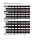
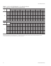
Refer toTable 1for UnitApplication Dataand to Table2 forGas
Heat Application Data.
If components are to be added to a unit to meet local codes, they
areto be installedat thedealer's and/ or the customer'sexpense.
Size of unit for proposed installation should be based on heat
loss / heat gain calculation made according to the methods of
Air Conditioning Contractors of America (ACCA).
LOCATION
Use the following guidelines to select a suitable location for
these units.
1. Unit is designed for outdoor installation only.
2. Condenser coils must have an unlimited supply of air.
Where a choice of location is possible, position the unit on
either north or east side of building.
WARNING:Excessive exposure of this furnace to contami
-
nated combustion air may result equipment dam
-
age or personal injury. Typical contaminates
include: permanent wave solutions, chlorinated
waxes and cleaners, chlorine based swimming
pool chemicals,water softeningchemicals, carbon
tetrachloride, Halogen type refrigerants, cleaning
solvents (e.g. perchloroethylene), printing inks,
paint removers, varnishes, hydrochloric acid, ce
-
ments and glues, antistatic fabric softeners for
clothes dryers, masonry acid washing materials.
3. For ground level installation, a level pad or slab should be
used.The thicknessand sizeof thepad orslab usedshould
meet local codes and unit weight. Do not tie the slab to the
building foundation.
4. Roof structures must be able to support the weight of the
unit and its options and / or accessories. Unit must be
installed on a solid level roof curb or appropriate angle iron
frame.
CAUTION: If a unit is to be installed on a roof curb or special
frame other than a YORK roof curb, gasketing
mustbe appliedto allsurfaces thatcomein contact
with the unit underside.
5. Maintainlevel tolerance to 1/2" maximum across the entire
length or width of the unit.
6. Elevate the unit sufficiently to prevent any blockage of the
air entrances by snow in areas where there will be snow
accumulation. Check the local weather bureau for the
expected snow accumulation in your area.
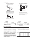
RIGGING AND HANDLING
Exercise care when moving the unit. Do not remove any
packaging until the unit is near the place of installation. Rig the
unit by attaching chain or cable slings to the lifting holes
provided in the base rails. Spreaders, whose length exceeds
the largest dimension across the unit, MUST be used across
the top of the unit.
BEFORE LIFTING A UNIT, MAKE SURE THAT ITS WEIGHT
IS DISTRIBUTED EQUALLY ON THE CABLES SO THAT IT
WILL LIFT EVENLY.
Units may also be moved or lifted with a forklift. Slotted
openings in the base rails are provided for this purpose.
LENGTH OF FORKS MUST BE A MINIMUM OF 42".
Remove the nesting brackets from the four corners on top of
the unit. All screws that are removed when taking these
brackets off must be replaced on the unit.
CAUTION: An adhesive backedlabel is provided overthe out-
side of the combustion air inlet opening to prevent
moisture from entering the unit which could cause
damage to electrical components. Allow this clo-
sure label to remain in place until the combustion
air hood is to be installed (refer to Figure 6).
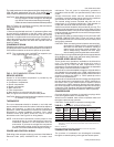
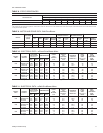
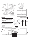
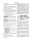
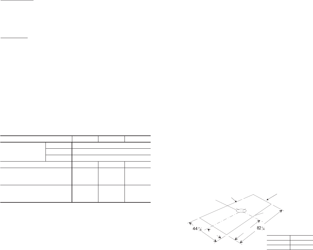
Referto Table4 forunit weightsand toFigure 1for approximate
center of gravity.
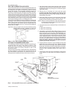
CLEARANCES
All units require certain clearances for proper operation and
service. Installer must make provisions for adequate
combustion and ventilation air in accordance with Section 5.3,
Air for Combustion and Ventilation of the National Fuel Gas
Code, ANSI Z223.1 (in U.S.A.) or Sections 7.2, 7.3 or 7.4 of
Gas Installation Codes CAN/CGA-B149.1 and .2 (in Canada)
and/or applicable provisions of the local building codes. Refer
to Figure 9 for the clearances required for combustible
construction, servicing, and proper unit operation.
WARNING:Do not permit overhanging structures or shrubs to
obstruct condenser air discharge outlet, combus
-
tion air inlet or vent outlet.
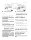
DUCTWORK
Ductwork should be designed and sized according to the
methods in Manual Q of the Air Conditioning Contractors of
America (ACCA).
A closed return duct system shall be used. This shall not
preclude use of economizers or outdoor fresh air intake. The
supply and return air duct connections at the unit should be
madewith flexiblejoints tominimize thetransmissionof noise.
035-14832-003-A-0204
Unitary Products Group 3
INSTALLATION
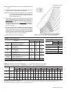
Model DEG 036 048 060
Voltage Variation
Min. / Max.
1
208/230V 187 / 253
460V 414 / 506
575V 518 / 630
Supply Air CFM, Nom. 1200 1600 2000
Wet Bulb Temperature (°F) of
Air on Evaporator Coil,
Min. / Max.
57 / 72 57 / 72 57 / 72
Dry Bulb Temperature (°F) of
Air on Condenser Coil,
Min
2
/ Max.
45 / 120 45 / 120 45 / 120
1
Utilization range “A” in accordance with ARI Standard 110.
2
Alow ambient accessory is available for operation down to 0°F.
TABLE 1 - UNIT APPLICATION DATA
APPROXIMATE
CENTER OF
GRAVITY
FRONT
67-3/4
30
30-1/2
15-1/8
FIG. 1 - CENTER OF GRAVITY
“
B
“
A
CONDENSER
COIL END
BACK
DIM. 3-5 TON
A 19-3/4"
B 40-3/4"