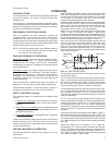
WARNING:Troubleshooting of components necessarily re
-
quires opening the electrical control box with the
power connected to the unit. Use extreme care
when working with live circuits! Check the unit
nameplate for the correct line voltage and set the
volt meter to the correct range before making any
connections with line terminals.
CAUTION: The wire number or color and terminal designa
-
tions referred to may vary. Check the wiring label
inside the control box access panel for the correct
wiring.
1. Draft motor operates and furnace lights but supply air
blower does not start after a short time delay with room
thermostat fan switch set to “AUTO”.
a. Set fanswitch to“ON”.If blowermotor runs,goto Stepf.
If it does not, check to see if line voltage is being sup
-
plied to the contacts of the blower relay, “BR”, andif the
blower relay is pulled in. Check for loose wiring.
b. If “BR” is pulled in, touch the supply air blower motor
housing. Ifit is hot themotor may beoff on inherentpro
-
tection. Disconnect power to the unit and check the
blower motor capacitor. If it is defective, replace it with
one of equal capacitance and voltage.
c. If “BR” is pulled in and the blower motor still does not
run, replace the blower motor.
d. If “BR” is not pulled incheck for 24 volts at the “BR”coil.
If 24 volts is present, replace the “BR” relay.
e. If 24 volts is notpresent at the “BR” coil, checkfor loose
24volt wiringback tothe relayboard. Checkcontrol wir-
ing tothe roomthermostat. Ifall isfine, replacethe relay
board.
f. If the blower motor runs with the fan switch in the “ON”
position but does not run soon after the furnace has ig-
nited with the fan switch in the “AUTO” position, check
for loose 24 volt wiring between the relay board in the
main control box, the Mate-N-Lok connector in the par
-
tition between the evaporator and gas heat sections
and the time delay relay “BT” or “ETD”.
g. If all control wiring is fine, check for 24 volts at the relay
board. If 24 volts is present, replace the relay board. If
24 volts is not present, replace the “BT” or “ETD”.
NOTE: The furnace may shut itself down on a high temperature
condition during the procedure but this will not effect the
test if it is done within 5 minutes of furnace shut-down.
2. Thesupply air bloweroperates but the draftmotor does not
when the room thermostat is set to call for heat and the fan
switch in the “ON” position.
a. The draft motor has inherent protection. If the motor shell
ishot tothe touch, waitfor the internaloverload toreset.
b. If themotor shelliscold withtheroom thermostatcalling
for heat, check for line voltage at the motor's Mate-N-
Lok connector attached to the evaporator partition. If
line voltage is present, replace the draft motor.
c. If linevoltage isnot present,check forline voltageat the
draft motor relay “DMR” or “DMC” contacts in the main
control box and check to see if the “DMR” or “DMC” is
pulled in.
d. If the “DMR” or “DMC” relay is pulled in, check for a
loose line voltage connection.
e. If the “DMR” or “DMC” relay is not pulled in, check for 24
volts at the “DMR” or 24 volts at “TMC-G” terminal coil. If
24 volts is present, replace the “DMR” or “DMC” relay. If
24 volts is not present, check for a loose 24 volt connec
-
tion back to the relay board and check the connections
from the room thermostat to therelay board. If allconnec
-
tions are correct, replace the relay board.
3. The draft motor runs but the furnace does not light and the
sparker does not spark.
a. Check all 24 volt connections from the relay board to
and in thegas heat section. Check lowvoltage connec
-
tionsto the“BT" and“DMC” or“ETD” locatedin thecon
-
trol box.
b. If the furnace is hot, it may be out on an over tempera
-
ture condition, wait for limit reset.
c. With thedraft motorrunning, check for24 voltsat termi
-
nal 24V on the ignitor control (IC) where the red lead
from the draft motor attaches. If 24 volts is not present,
the centrifugal switch (CS) has not closed or has gone
bad. Check the line voltage to the unit, if it is correct re
-
place thedraft motor.If linevoltage islow callthe power
company.
d. If 24 volts ispresent at the ignitorcontrol, check all con
-
trol wiringat theignitor controland thehigh tensionwire
to the ignitor. Check that the green ground wires from
the ignitor control, the gas valve and pilot burner are all
intact and making good electrical connection. Check to
make sure that the ceramic insulator on the pilot ignitor
or sensor is not broken or cracked, if all are intact re-
place the ignition control “IC”.
4. The draft motor runs and the sparker sparks at the pilot
burner but the pilot does not ignite and a gas odor is not
detected at the draft motor outlet.
a. Check to make sure gas is being supplied to the unit.
Make sure that the gas pressure to theunit is within the
proper limits as described in the “POST START
CHECK LIST”and thatthe pilotadjust screwis allowing
someflow ofgas asdescribed in“PILOTCHECKOUT”.
b. Check all wiringbetween the ignitorcontrol and thegas
valve. Check to make sure the ground connections are
intact.
c. If thewiring isintact, check for24 voltsacross terminals
“PV” and“COMMON” onthe ignitorcontrol. If24 voltsis
not present, replace the ignitor control.
d. If 24 volts is present, remove the pilot burner and re
-
move the pilotorifice from thepilot burner. The orificeis
removed in the direction opposite the flow of gas. In
-
spect the orifice for obstruction. If it is clear, replace the
main gas valve.
5. Thesparker sparks at the pilotburner but the pilot doesnot
ignite and a gas odor is detected at the draft motor outlet.
a. Adjust the pilot adjust screw on the gas valve as de
-
scribed in “PILOT CHECKOUT”.
b. Check the supply pressure as described in “POST
START CHECK LIST”. Make adjustments as neces
-
sary.
c. Check the pilot orifice for obstruction as described in
Item 4. Clean as needed but the problem should not be
the gas valve.
18 Unitary Products Group
035-14832-003-A-0204
TROUBLESHOOTING
Cont'd