3. Use wrought iron or steel pipe for all gas lines. Pipe dope
should be applied sparingly to male threads only.
CAUTION: If flexible stainless steel tubing is allowed by the
authority having jurisdiction, wrought iron or steel
pipe must be installed at the gas valve and extend a
minimumoftwo(2)inchesoutsideoftheunitcasing.
WARNING:Natural gas may contain some propane. Propane,
being an excellent solvent, will quickly dissolve
white lead or most standard commercial com
-
pounds. Therefore, a special pipe dope must be
applied when wrought iron or steel pipe is used.
Shellacbasecompoundssuch asGaskolacorSta
-
lastic, and compounds such as Rectorseal #5,
Clyde's or John Crane may be used.
4. Allpipingshould becleanedofdirt andscaleby hammering
on theoutsideof thepipe andblowing outthe loosedirt and
scale. Before initialstart-up, be sure that allof the gas lines
external to the unit have been purged of air.
5. The gas supply should be a separate line and installed in ac
-
cordance with all safety codes as prescribed under “Limita
-
tions”. After the gas connections have been completed, open
the main shut-off valve admitting normal gas pressure to the
mains. Check all joints for leaks with soap solution or other
material suitable for the purpose. NEVER USE A FLAME.
6. The furnace and its individual manual shut-off valve must
be disconnected from the gas supply piping system during
any pressure testing of that system at test pressures in ex-
cess of 1/2 psig (3.48 kPa).
The furnace must be isoulated from the gas supply piping
system by closing its individual manual shut-off valve dur-
ing any pressure testing of the gas supply piping system at
test pressures equal to or less than 1/2 psig (3.48 kPa).
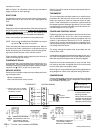
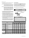
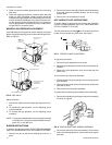
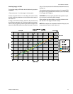
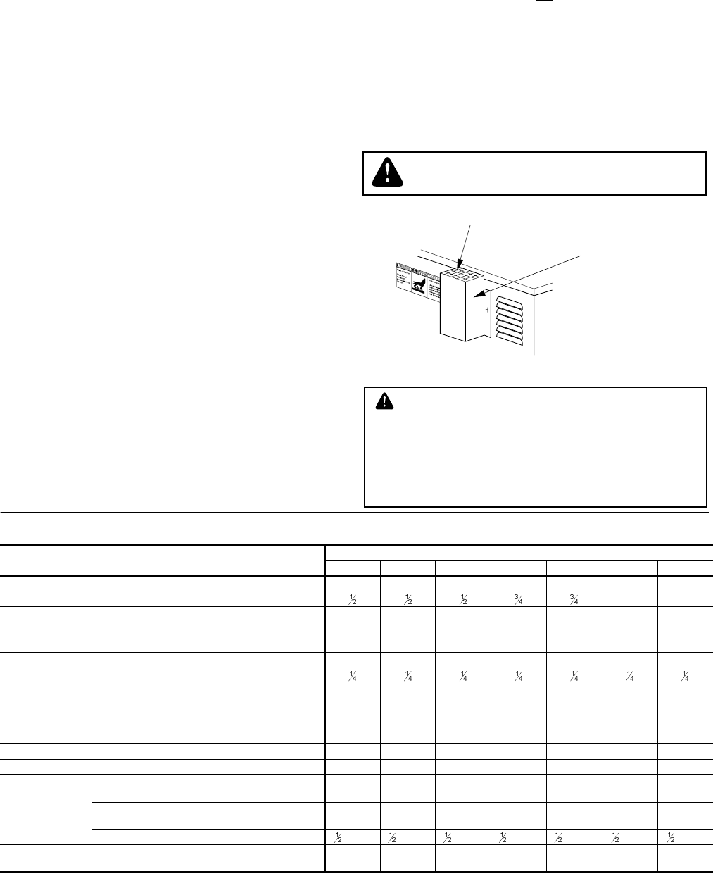
FLUE VENT HOOD
Theflue venthoodwithscreenis notshippedattached.This hood
must be installed to assure proper unit operation. The hood must
be fastened to the outside of the side gas control/electrical com
-
partment with the screws provided in the bag attached to the in
-
side of the gas control/electrical compartment, see Figure 3.
The unit is controlled by a conventional four wire heating/cool
-
ing thermostat common to this class of equipment.
035-18265-001-A-0202
6 Unitary Products Group
VENT OUTLET SCREEN
FLUE VENT OUTLET
AIR HOOD
FIG. 3 - FLUE VENT OUTLET AIR HOOD
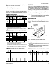
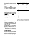
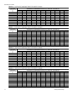
TABLE 6 - PHYSICAL DATA
MODELS
DNA
018 024 030 036 042 048 060
EVAPORATOR
BLOWER
CENTRIFUGAL BLOWER (Dia. x Wd. in.) 10 X 8 10 X 8 10 X 8 11 x 10 11 x 10 12 x 11 12 x 11
FAN MOTOR HP (Three Speed)
1.0 1.0
EVAPORATOR
COIL
ROWS DEEP 2222333
FINS PER INCH 14 13 13 15 13 13 13
FACE AREA (Sq. Ft.) 2.25 3.5 3.5 3.5 3.5 4.5 4.5
CONDENSER
FAN
PROPELLER DIA. (in.) 22 22 22 22 22 22 22
FAN MOTOR HP
NOM. CFM TOTAL 1,800 2,200 2,400 2,400 2,400 3,000 3,000
CONDENSER
COIL
ROWS DEEP 1111111
FINS PER INCH 13 13 16 20 20 20 20
FACE AREA (Sq. Ft.) 8.3 8.3 11.7 11.7 11.7 14.8 14.8
CHARGE REFRIGERANT 22 (lbs./oz.) 3 / 2 3 / 6 4 / 12 4 / 3 4 / 12 6 / 0 5 / 4
FILTER* FACE AREA (Sq. Ft.) / SIZE (NOMINAL) 2.6/20x20 2.6/20x20 2.6/20x20 2.6/20x20 2.6/20x20 3.3/20x12 3.3/20x12
FURNACE
SECTION
NATURAL GAS BURNER ORIFICE NO.
(Qty./Drill size)
43 43 43 43 43 40 40
PROPANE BURNER ORIFICE NO.
(Qty./Drill size)
55 55 55 55 55 53 53
GAS CONNECTION SIZE
NPTI NPTI NPTI NPTI NPTI NPTI NPTI
COMPRESSOR
TYPE
HERMETICALLY SEALED
(R = RECIPROCATING, S = Scroll)
RRRRRSS
* = Three phase 018 thru 042 size units are supplied with one (1) filter and on three phase 048 and 060 size units two (2) filters are supplied. Single phase units are shipped without filters.
See “FILTERS” on page 4.
WARNING: FLUE HOOD SURFACES
MAY BE HOT.
CAUTION
The flue exhaust hood must be properlyinstalled andwithin the
recommended clearances. Further communications and action
must be given to the home or building owner(s) to eleiminate
any unauthorized humon contact around this area during the
heating cycle. Flue hood surface and immediate area is de-
signedtooperateathightemperaturesduringtheheatingcycle.