Scroll compressors operate in one direction only. If a three
phase scroll compressor is experiencing:
•
Low amperage draw
•
Similar discharge and suction pressures
•
Increased noise level
then the compressor is operating in reverse. To correct this
condition,switch anytwo (2)linevoltage leadsat thecontactor.
Please note, single phase scroll compressor will start and run
in one direction only. The reverse operation is not a concern.
COMBUSTION DISCHARGE
GAS PIPING
Proper sizing of gas piping depends on the cubic feet per hour
ofgasflowrequired,specific gravityofthegasandthelengthof
run. “National Fuel Gas Code” Z223.1 or CAN/CGA B149.1 or
.2 should be followed in all cases unless superseded by local
codesorgascompanyrequirements.RefertoTables4and5.
The heating value of the gas may differ with locality. The value
should be checked with the local gas utility.
NOTE: There maybea localgasutilityrequirement specifying
a minimum diameter for gas piping. All units require a
1/2 inch pipe connection at the gas valve.
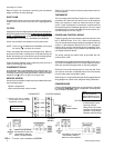
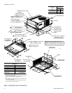
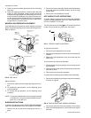
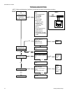
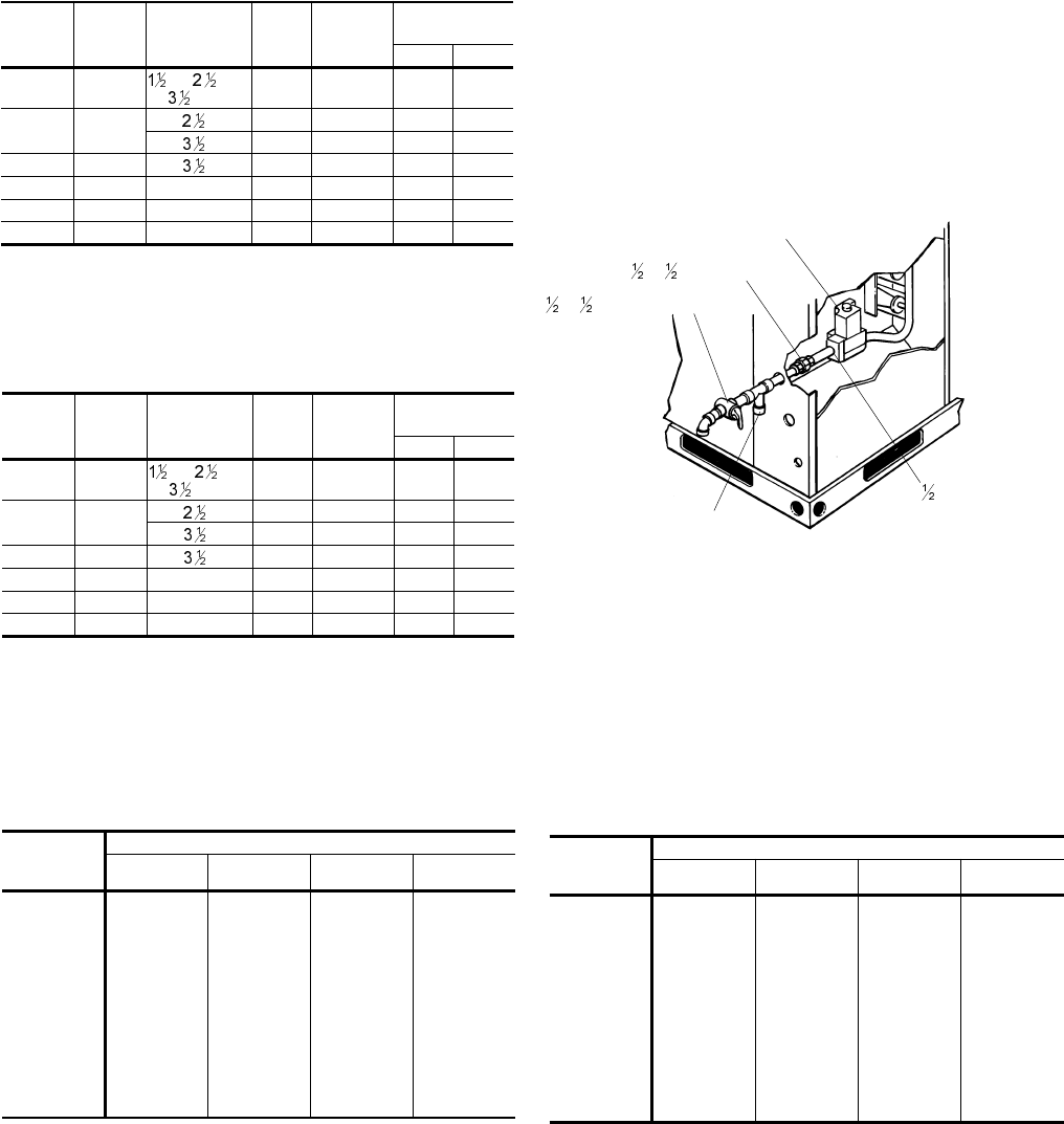
GAS CONNECTION
The gas supply line can be routed through the hole located on
the left sideof theunit. Referto Figure 5to locatethese access
openings. Typical supply piping arrangements are shown in
Figure 2.
Gas piping recommendations:
1. Adrip leg and a ground joint union must be installed in the
gas piping.
2. Whenrequiredby localcodes,a manualshut-offvalvemay
have to be installed outside of the unit.
035-18265-001-A-0202
Unitary Products Group 5
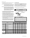
FIG. 2 - EXTERNAL SUPPLY CONNECTION
EXTERNAL SHUT-OFF
x
UNION
x
GAS COCK
AUTOMATIC
GAS VALVE
- 14 NPT
DRIP LEG
Input
Capacity
(Mbh)
3
Output
Capacity
(Mbh)
Available
On
Models
Gas
Rate
1
Ft.
3
/Hr.
Number
of
Burners
Temp. Rise °F
At Full Input
2
Min. Max.
45 36
, 2, , 3 &
TON
42 2 25 55
70 56
2 &
TON 65 3 30 60
3 &
TON 65 3 25 55
90 72 3 &
TON 84 4 30 60
80 64 4 & 5 TON 74 3 25 55
108 86 4 & 5 TON 100 4 30 60
135 108 4 & 5 TON 126 5 35 65
1 Based on 1075 BTU/Ft.
3
.
2 The air flow must be adjusted to obtain a temperature rise within the range shown.
Continuous return air temperatures should not be below 55°F.
3 Heating capacity valid for elevations up to 2000 feet above sea level. For elevations
above 2000 feet, rated capacity should be reduced by 4% for each 1000 feet above sea
level.
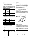
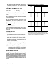
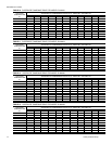
TABLE 2 - NATURAL GAS APPLICATION DATA
Input
Capacity
(Mbh)
3
Output
Capacity
(Mbh)
Available
On
Models
Gas
Rate
1
Ft.
3
/Hr.
Number
of
Burners
Temp. Rise °F
At Full Input
2
Min. Max.
45 36
, 2, , 3 &
TON
18 2 25 55
70 56
2 &
TON 28 3 30 60
3 &
TON 28 3 25 55
90 72 3 &
TON 36 4 30 60
80 64 4 & 5 TON 32 3 25 55
108 86 4 & 5 TON 43 4 30 60
135 108 4 & 5 TON 54 5 35 65
1 Based on 2500 BTU/Ft.
3
.
2 The air flow must be adjusted to obtain a temperature rise within the range shown.
Continuous return air temperatures should not be below 55°F.
3 Heating capacity valid for elevations up to 2000 feet above sea level. For elevations
above 2000 feet, rated capacity should be reduced by 4% for each 1000 feet above sea
level.
4 Propane applications are accomplished by field installation of a Propane Conversion
Accessory, Model 1NP0805 for 1.5 thru 3.5 ton units and Model 1NP0806 for 4 and 5
ton units.
TABLE 3 - PROPANE (LP) GAS APPLICATION DATA
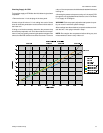
Length
in
Feet
Nominal Inches Iron Pipe Size
1/2 in. 3/4 in. 1 in. 1-1/4 in.
10 132 278 520 1,050
20 92 190 350 730
30 73 152 285 590
40 63 130 245 500
50 56 115 215 440
60 50 105 195 400
70 46 96 180 370
80 43 90 170 350
90 40 84 160 320
100 38 79 150 305
Maximum Capacity of Pipe in Cubic Feet of Gas Per Hour (Based Upon APressure Drop
of 0.3 Inch Water Column and 0.6 Specific Gravity Gas).
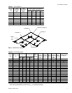
TABLE 4 - NATURAL GAS PIPE SIZING CHART
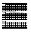
Length
in
Feet
Nominal Inches Iron Pipe Size
1/2 in. 3/4 in. 1 in. 1-1/4 in.
10 275 567 1,071 2,205
20 189 393 732 1,496
30 152 315 590 1,212
40 129 267 504 1,039
50 114 237 448 913
60 103 217 409 834
70 96 196 378 771
80 89 185 346 724
90 83 173 322 677
100 78 162 307 630
Maximum Capacity of Pipe in Thousands of BTU Per Hour (Based Upon APressure Drop
of 0.5 Inch Water Column).
TABLE 5 - PROPANE (LP) GAS PIPE SIZING CHART