9
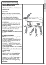
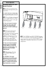
General wiring guidelines for safe and
secure wire connections:
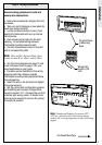
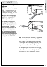
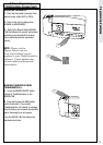
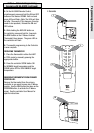
• Ends of wires should be stripped 3/8 inch
as shown.
• Take care not to damage or lose labels for
each wire during handling.
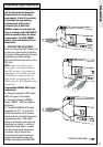
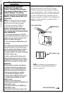
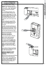
• Locate and dress wires to come in from
behind the thermostat and turn up into the
terminal area.
• Push excess wiring back into the wall
opening. Do not allow wiring between
thermostat mounting base and wall.
• Connect labeled wires only to a terminal
with a corresponding letter.
Note: Be careful, do not allow bare
wires to touch, or short, each other.
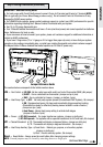
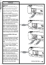
• Use the wiring diagrams on page 12 and
cross reference chart on page 13 for your
exact application as your guide.
• Fan wires out as illustrated in the wiring
diagrams with the Z-Wave® enabled
thermostat mounting base positioned below
the wall opening.
• Insert the wire in the terminal and tighten
the screw securely.
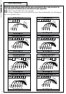
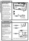
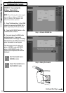
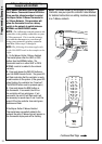
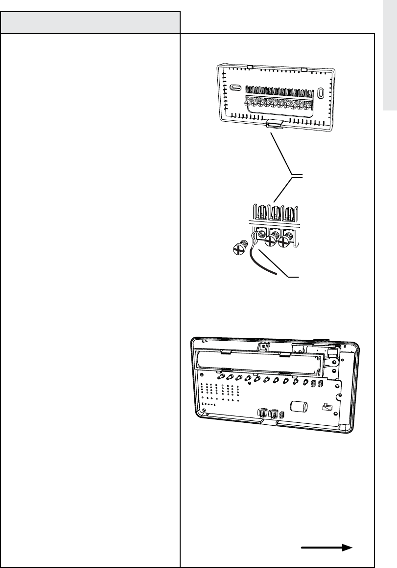
• Set the control unit configuration jumpers
per the Wiring and Jumper configurations
found on pages 14-17, choosing the one that
matches your wiring needs. A needle-nose
pliers may be required to remove the jumper
to modify its position.
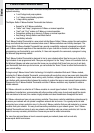
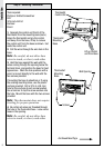
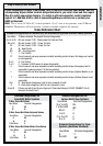
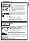
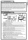
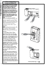
Step 4: Wiring Information
Installation
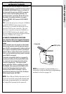
Terminal Block
in Mounting
Base
Wiring Strip
length is 3/8
inch
Note:
Numbered Jumper Locations JP1 -
JP5 are referenced in illustration above
and in the wiring diagrams on the following
pages.
Continued Next Page
JP1
JP2
JP5
JP3
JP4