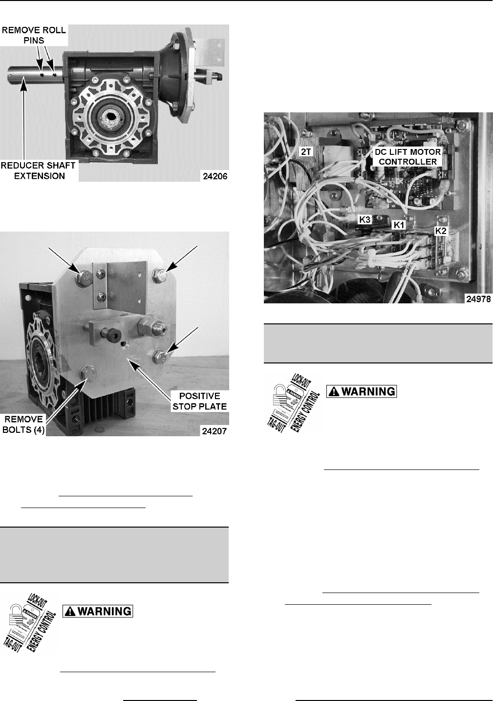
Fig. 21
8. Remove positive stop plate from gear reducer.
Note that the positive stop shaft is keyed.
Fig. 22
9. Reverse procedure to install replacement gear
reducer.
10. Perform KETTLE TILT ADJUSTMENT -
MANUAL TILTING MODELS to check for proper
operation.
ELECTRICAL PANEL
COMPONENTS - POWER TILTING
OPTION ONLY
Disconnect the
electrical power to the machine and
follow lockout / tagout procedures.
1. Remove
CONTROL BOX COVER (TILTING).
2. Disconnect lead wires from component being
replaced.
3. Remove screws securing the component to
panel.
4. Reverse procedure to install and check for proper
operation.
Fig. 23
TILT SWITCH (2S) - POWER
TILTING OPTION ONLY
Disconnect the
electrical power to the machine and
follow lockout / tagout procedures.
1. Place kettle in the fully upright position.
2. Remove
CONTROL BOX COVER (TILTING).
3. Note lead wire locations and disconnect from tilt
switch (2S).
4. Remove adjustment screws (2) securring switch
bracket to mounting plate.
5. Remove mounting nuts and screws (2) securring
tilt switch (2S) to bracket.
6. Reverse procedure to install tilt switch (2S).
7. Perform TILT SWITCH (2S) ADJUSTMENT -
POWER TILTING OPTION ONLY.
K Series Gas Kettles 2/3 Jacketed Stationary and Tilting - REMOVAL AND REPLACEMENT OF PARTS
F45461 Rev. A (0713) Page 14 of 44
