2-20
Installing the Switch
Installation Procedures
Installing the Switch
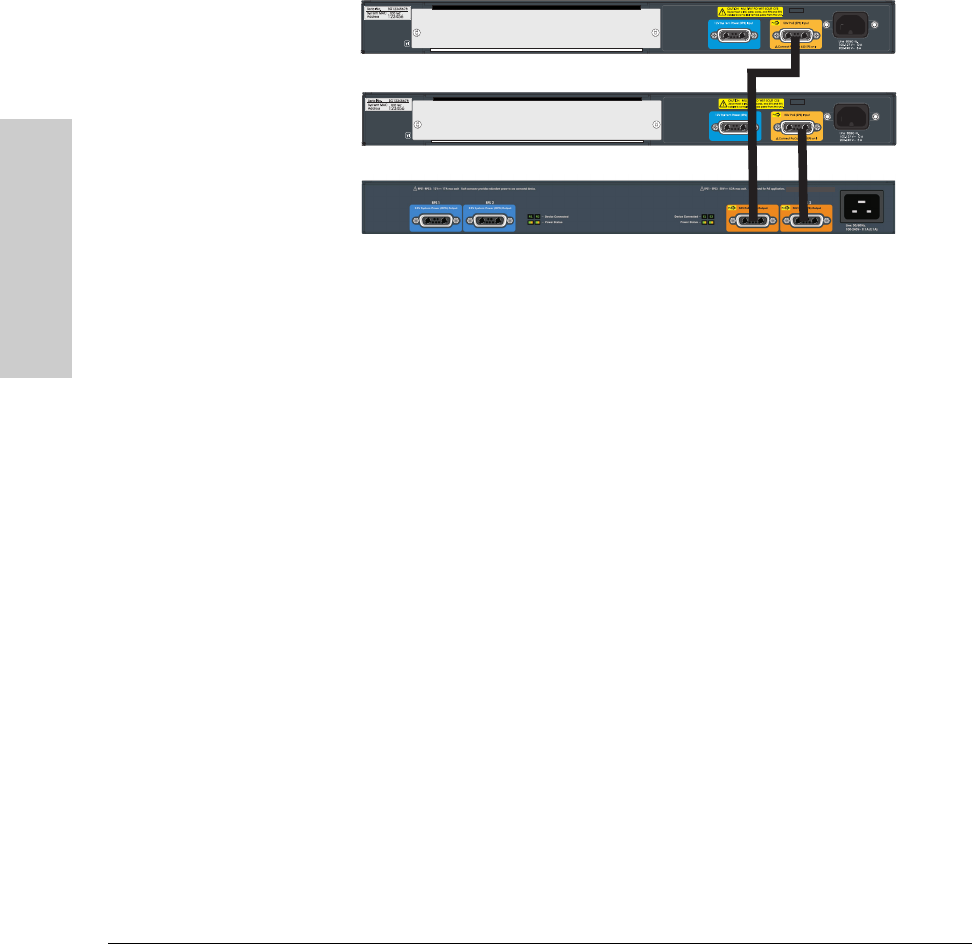
The 620 RPS/EPS is designed to provide primary or backup power to up to
two HP ProCurve PoE switches. In the following illustration, two HP ProCurve
3500yl-24G-PWR switches are being supplied with external PoE power from
an 620 RPS/EPS. The switches provide PoE power to Ethernet devices
connected to their ports.
Figure 2-14. Connecting EPS to two 24-port switches.
10. Connect a Console to the Switch (Optional)
The switch has a full-featured, easy to use console interface for performing
switch management tasks including the following:
■ monitor switch and port status and observe network activity statistics
■ modify the switch’s configuration to optimize switch performance,
enhance network traffic control, and improve network security
■ read the event log and access diagnostic tools to help in troubleshooting
■ download new software to the switch
■ add passwords to control access to the switch from the console, web
browser interface, and network management stations
The console can be accessed through these methods:
■ Out-of-band: The switch comes with a serial cable for connecting a PC
or VT-100 terminal, to be used as a console, directly to the switch.
■ In-Band: Access the console using Telnet from a PC or UNIX station on
the network, and a VT-100 terminal emulator. This method requires that
you first configure the switch with an IP address and subnet mask by using
either out-of-band console access or through DHCP/Bootp. For more
information on IP addressing and on starting a Telnet session, see
chapter 3, “Getting Started With Switch Configuration”, and the Man-
agement and Configuration Guide, which is on the HP ProCurve Web
site at www.procurve.com/manuals.


