2-14
Installing the Switch
Installation Procedures
Installing the Switch
Equipment
Cabinet
Note
The 12-24 screws supplied with the switch are the correct threading for
standard EIA/TIA open 19-inch racks. If you are installing the switch in an
equipment cabinet such as a server cabinet, use the clips and screws that came
with the cabinet in place of the 12-24 screws that are supplied with the switch.
Complete step 1, and plan which four holes you will be using in the cabinet
and install all four clips. Then proceed to step 2.
Rack Mounting the Switch 3500yl-24G
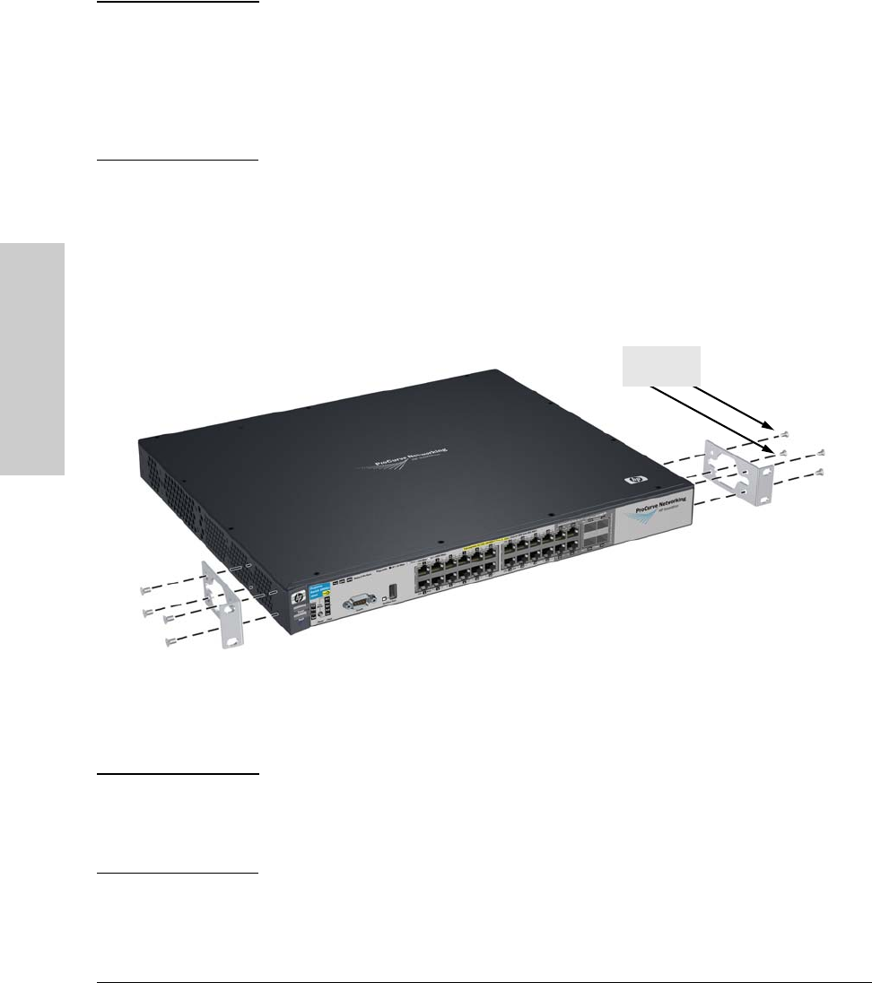
1. Use a #1 Phillips (cross-head) screwdriver and attach the mounting
brackets to the switch with the included 8-mm M4 screws.
Figure 2-7. Attaching the mounting brackets to the switch.
Note The mounting brackets have multiple mounting holes and can be rotated
allowing for a wide variety of mounting options. These include mounting the
switch so its front face is flush with the face of the rack, or mounting it in a
more balanced position as shown in the illustration.
8 mm
M4 screws


