Figure 5.
Figure 6.
5.
Figure 7
6.
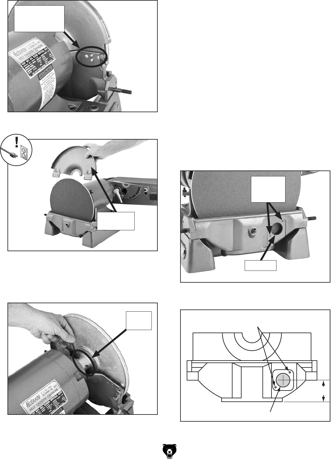
Note: It may be necessary to gently tap on
the back of the disc with a dead blow hammer
or rubber mallet to aid in removing it from the
shaft.
7. Figures 8–9
Important: Make sure the center of this hole
is 2
1
⁄8" above the bottom of the guard, as illus-
trated in Figure 9.
Note: Do not drill and tap the #10-24 holes
until the next step.
Figure 7.
Figure 8.
#10-24 Threaded Holes
1
3
⁄8" Hole
Lower
Disc Guard
2
1
⁄8"
Figure 9.


