Power Supply, High Voltage (HVPS)
1 Remove the back cover (see Figure 6-4).
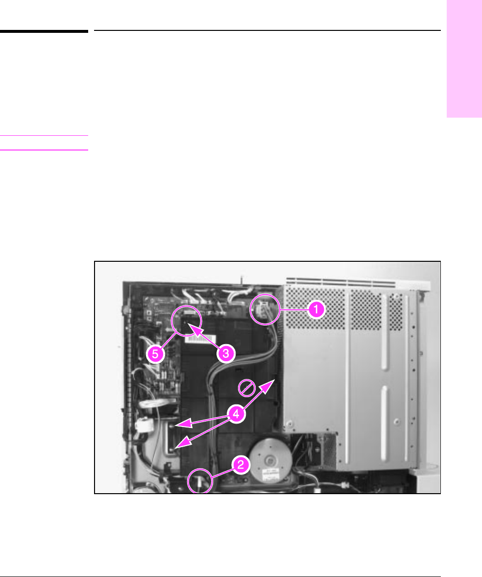
2 Unplug the cable from the LVPS to the DC Controller PCA (Figure 6-40,
callout 1), and move it out of the way.
3 Unplug the connector from the bottom of the HVPS (Figure 6-40, callout 2).
Note
DO NOT remove the screw indicated in Figure 6-40 by the null symbol (ø).
4 Remove (1) self-tapping screw, CH106 (Figure 6-40, callout 3), and (3)
screws, CH101 (Figure 6-40, callout 4).
To Reinstall:
Make sure that the plastic alignment pin (Figure 6-40, callout 5), the
connector pins and the high voltage contacts are properly aligned before
replacing the screws.
High Voltage Power Supply
Figure 6-40
6
Removal and
Replacement
Removal and Replacement 6-53