Reference Manual
300530EN, Rev BA
September 2012
Rosemount 2410
5-6
Section 5. Operation
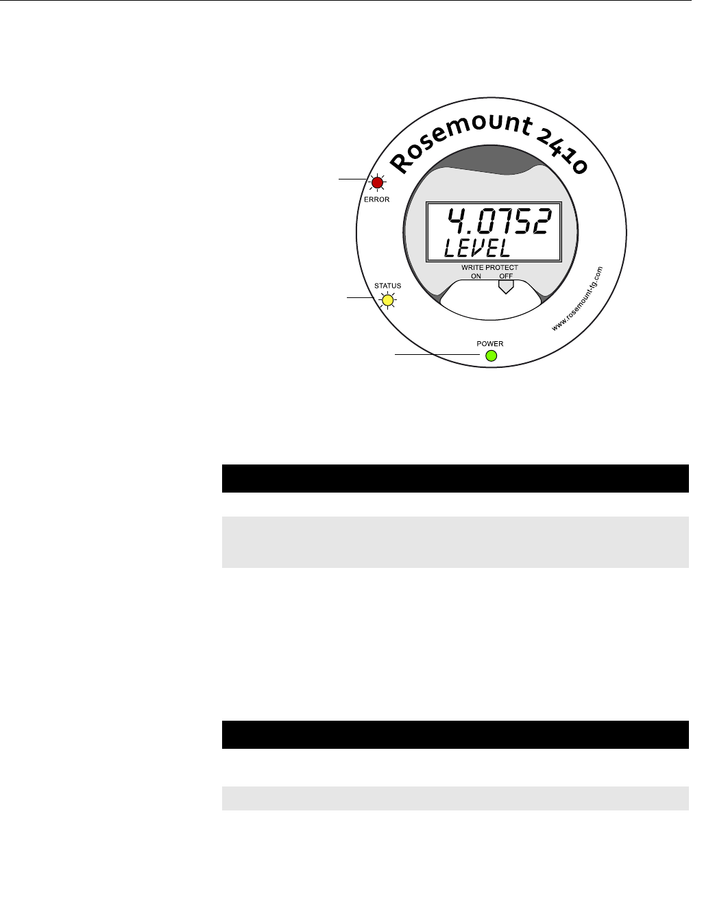
5.5 LED There are three Light Emitting Diodes (LED) on the Rosemount 2410 front for
status and error information.
Figure 5-3. The Rosemount
2410 has three LEDs
The following color codes are used for the 2410 LEDs:
Table 5-4. LED color codes
5.5.1 LED Start-Up
Information
When the 2410 is starting, both the Status and the Error LEDs indicate
possible hardware or software errors as shown in Table 5-5 below:
Table 5-5. LEDs are used for
error indication at 2410 start-up
Error LED (Red)
Status LED (Yellow)
Power On LED (Green)
LED Type Color Description
Power On Green The green LED indicates that the 2410 is powered on.
Status Yellow The yellow Status LED blinks at a constant rate of one flash
every other second in normal operation to indicate the the
2410 software is running
Error Red The red Error LED is turned off in normal operation. If an error
occurs, the Error LED flashes a sequence that corresponds to
a certain error code, see “LED” on page 5-6.
Error type Status LED Error LED Description
Hardware Blinking Blinking Status and Error are blinking
simultaneously
Checksum Blinking Blinking Status and Error are toggling
Other On Blinking Unknown error


