2-23
Catalyst 3750-X and 3560-X Switch Hardware Installation Guide
OL-19593-01
Chapter 2 Switch Installation
Connecting the StackPower Ports to the XPS-2200
Connecting the StackPower Ports to the XPS-2200
Before connecting the StackPower cables, review the “Planning a StackPower Stack (Catalyst 3750-X
Switches)” section on page 2-8. Always use a Cisco-approved StackPower cable to connect the switches.
To prevent misconfiguration, the StackPower ports on the switch and the XPS-2200 are keyed and have
colored stripes that match the keying and stripes on the StackPower cable ends.
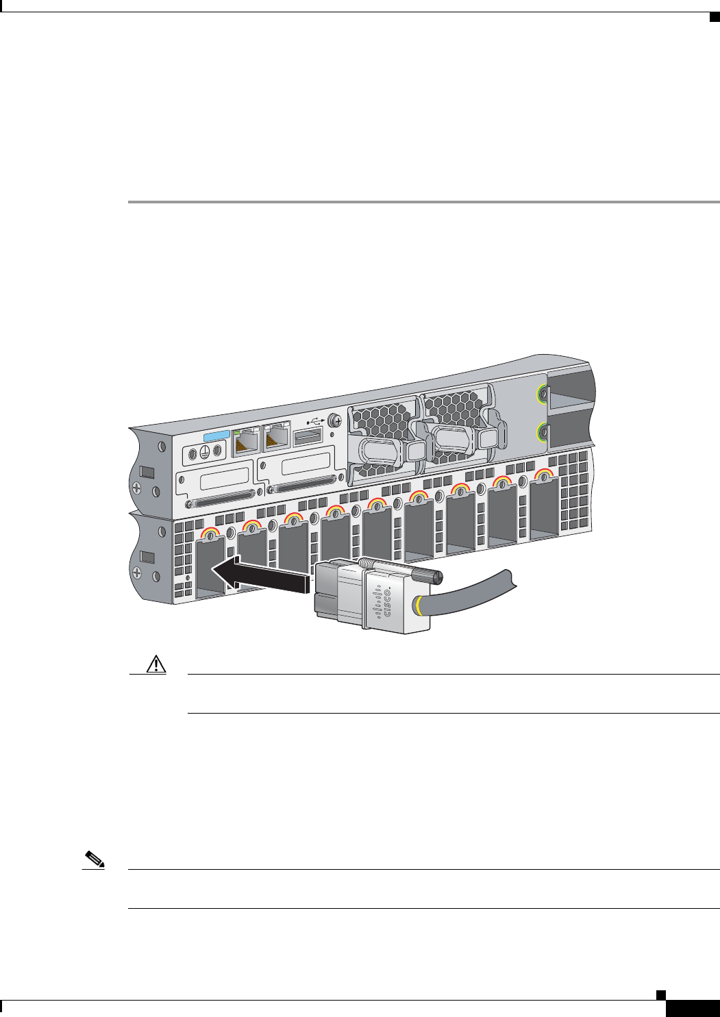
Step 1 Connect the end of the cable with a green stripe to the connector marked XPS on the switch. Align the
connector correctly, and insert the end of the cable with a green stripe into an XPS port on the switch
rear panel.
Step 2 Connect the end of the cable with a red or yellow stripe to an XPS-2200 power supply. (Figure 2-24)
Step 3 Hand-tighten the captive screws to secure the StackPower connectors in place.
Figure 2-24 Connecting the StackPower Cable to an XPS-2200 Port
Caution Removing and installing the StackPower cable can shorten its useful life. Do not remove and
insert the cable more often than necessary.
Installing a Network Module in the Switch
These sections describe how to install and remove 1-Gigabit Ethernet and 10-Gigabit Ethernet network
modules that provide uplink ports for the switch or the blank module, which provides no uplink ports.
See the
“Network Modules” section on page 1-4.
Note There must be a supported network module in the network module slot. If no uplink ports are required,
insert a blank network module. An empty slot generates error messages.
The network module is hot-swappable. If you remove a module, replace it with another network module.
R
E
S
E
T
1
2
3
4
5
6
7
8
9
CON
S
OL
E
RESE
T
AUX
STACK 1
STACK 2
S
-PWR
XPS
S-PWR
253672


