62
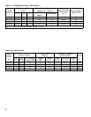
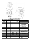
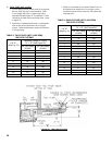
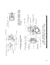
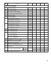
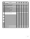
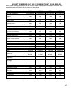
TABLE 8: BECKETT AFG BURNER SPECIFICATIONS
Boiler
Model
Burner
Input
(gph)
Head
Type
(setting)
Air
Shutter
(setting)
Air
Band
(setting) Nozzle
Pump
Pressure
(psi)
Approx.
Shipped
CO
2
(%)
Bafe
Location
(pass)
Approx.
Stack Temp.
Increase
Without
Bafes
(F)
2
Bafes
IN
Minimum
Breech
Pressure
("w.c.)
3
Bafes
OUT
Minimum
Breech
Pressure
("w.c.)
3
Bafes
IN
Minimum
Overre
Pressure
("w.c.)
3
Bafes
OUT
Minimum
Overre
Pressure
("w.c.)
3
MST288 0.75 L1 6
1
1
0.60 x 60A
Delavan
150 11.5 --- --- 0 0 --- 0.010
MST396 1.05 L1 7 1
0.85 x 60B
Delavan
150 11.5 2nd 20 0 0 0.040 0.020
MST513 1.35 V1 (0) 7 2
1.10 x 60B
Hago
150 11.5 2nd 40 0 0 0.040 0.030
MST629 1.65 V1 (3) 7 2
1.35 x 60B
Hago
150 11.5 2nd 52 0 0 0.050 0.030
Notes
1)
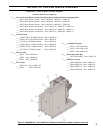
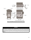
MST288 at 0.75 GPH ring rate utilizes a low re bafe.
2)
The increased stack temperature with the bafes removed is an approximation, based on a constant supply temperature of 212°F and 11.5% CO
2
. Actual eld conditions may be
different.
3) These values are minimum and could be as much as -.03" w.c., more without impacting performance. Pressures based on 11.5% CO
2
. Example: MST629 could have a breech pressure
of -.03" w.c. and an overre pressure of .020" w.c.
4) Single stage fuel pump is standard, two stage fuel pump is optional. Burner manufacturer has preset single stage fuel pump to settings shown in table above.
Two stage fuel pump is factory set at 140 PSI and must be readjusted to settings shown above during burner start-up.