Installation and Wiring
6
ENV-VST-C - Operation / Reference Guide
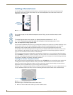
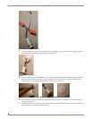
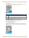
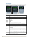
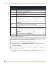
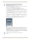
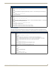
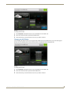
Preparing Captive Wires
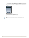
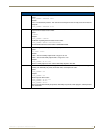
Follow these steps to connect the wiring into a captive-wire connector:
1. Strip 1/4 inch off the wire insulation for all four wires.
2. Tin 2/3 of the exposed wire.
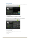
3. Insert each wire into the appropriate captive-wire connector up to the insulation.
4. Tighten the captive screws to secure the fit in the connector.
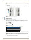
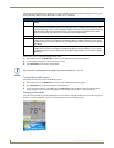
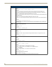
Wiring Guidelines
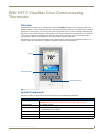
The ViewStat Color Communicating Thermostat accepts configuration and weather information from a NetLink
Integrated master via an AxLink bus. Use 18 AWG wire to connect terminals L1-L4 on the ViewStat to the AxLink
device.
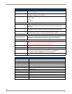
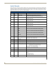
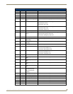
See the Communication and Equipment Terminal Wiring Definitions section on page 5 for more information on the
terminals on the ViewStat.
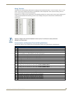
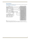
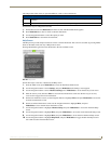
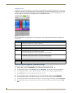
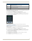
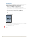
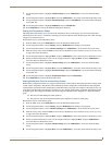
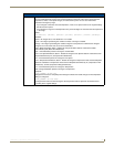
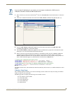
Wiring for AxLink
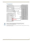
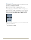
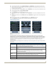
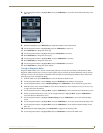
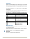
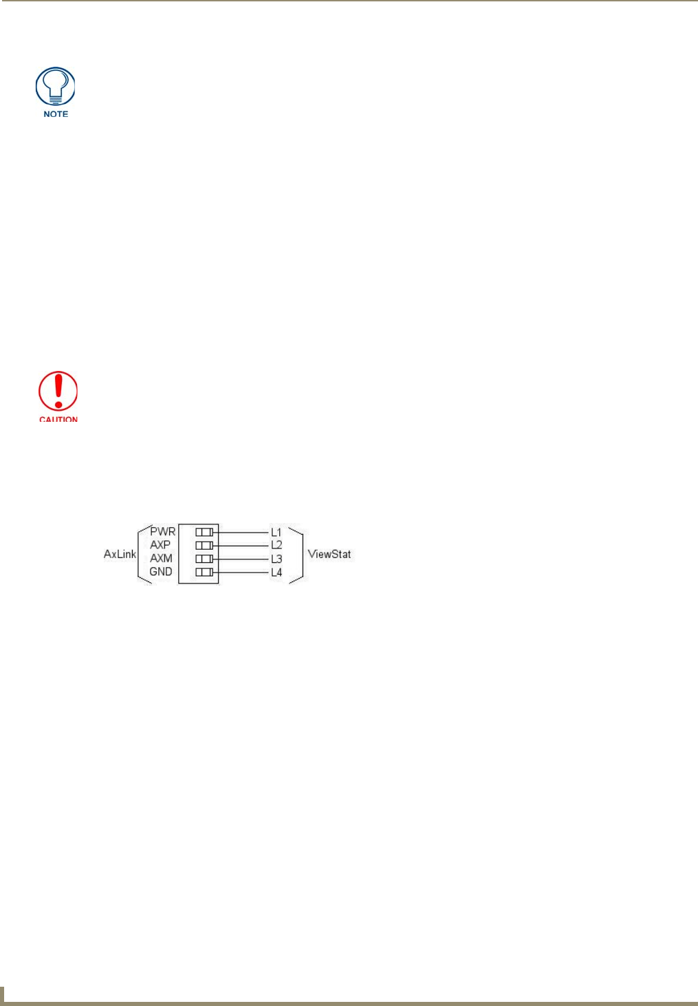
Connect the AxLink wiring from the thermostat to the connector on the AxLink device as shown in FIG. 3.
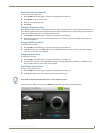
You can connect the AxLink device to a NetLinx Master by following the instructions in the AxLink device’s instruction
manual.
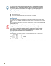
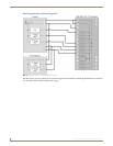
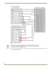
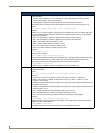
On older model Color ViewStat thermostats, the 2nd stage heat on Two Stage Heat Pump systems
wires to the W2 terminal. On newer thermostat models, 2nd stage heat wires to the Y2 terminal. If
you replace an older model thermostat with a newer model, you must rewire the terminals for two
stage heat pumps. Failure to do so could result in 2nd stage heating not working properly.
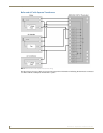
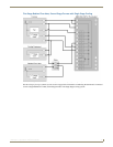
The ViewStat Color Communicating Thermostat interfaces with a 24 VAC power supply from the
heating/cooling unit through its RC terminal. You should not connect the power wiring from the
AxLink device to the thermostat with the intent of using the AxLink device to provide power to the
thermostat.
The L1 terminal on the thermostat can accept the AxLink +12VDC wire and you can connect the
wire to the terminal if you want to assure there are no loose wires inside the thermostat, but you
should not power the thermostat by running a jumper to the RC pin.
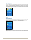
FIG. 3 AxLink wiring