TESTING THE DOOR OPERATION
When the basic wiring is complete the door
operation may be tested. It may be helpful to fit
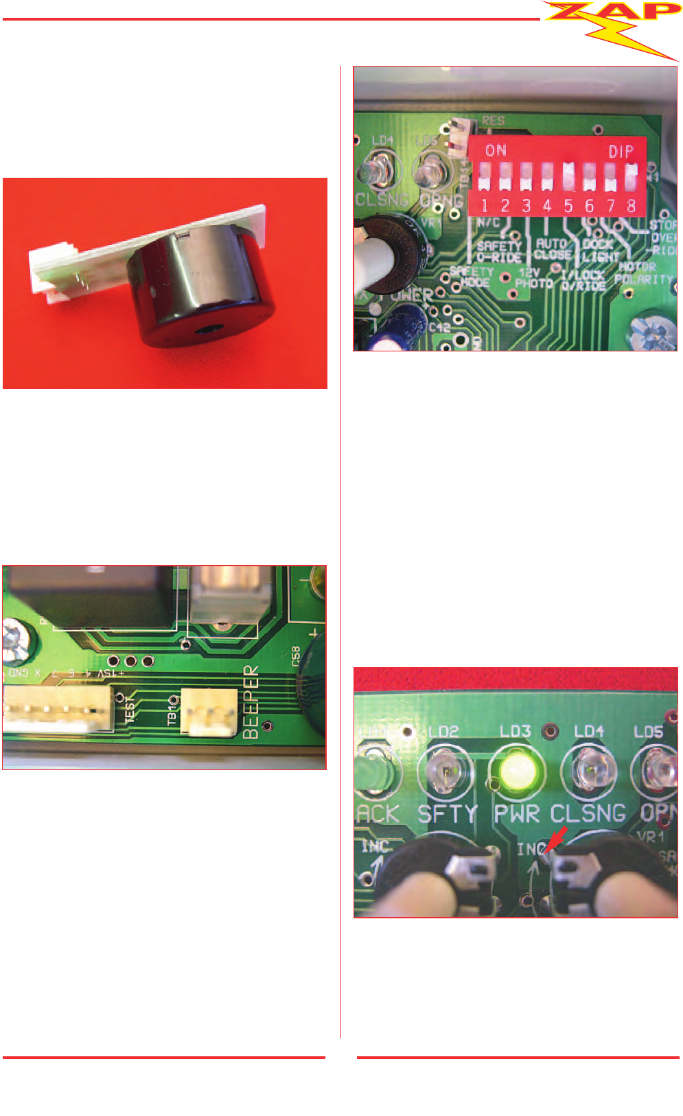
an optional Plug-in Beeper module (part No. 850)
(Pic 28), which sounds in conjunction with flashes
of the Acknowledge LED. The beeper will sound at
the start of each door movement and provides
audible feedback during programming and door
position calibration. The Beeper is fitted into the
white 3- way socket at the upper left hand side of
the panel market TB1 – Beeper (Pic 29).
A momentary press of the case lid push button or
a remote push button, if fitted, operates the door.
The push button operation is: PRESS TO OPEN –
PRESS TO STOP – PRESS TO CLOSE – PRESS TO STOP.
The push button may be used to switch on a light,
if fitted, when the door is closed and without
moving the door, by an extended press of the push
button for 2
1
/2 seconds until the light illuminates.
Note the factory set positions of each of the DIP
switches at the top right hand side of the panel
will be: (Pic 30)
SW1 SAFETY MODE OFF/N/C
SW2 STANDARD SAFETY OFF
SW3 12V PHOTO-EYE OFF
SW4 AUTO-CLOSE OFF (NOT USED)
SW5 INTERLOCK OVER-RIDE ON
SW6 LIGHTING MODE OFF
SW7 MOTOR POLARITY AS REQUIRED
(See next paragraph)
SW8 STOP BUTTON OVER-RIDE ON
(A separate Stop button is not fitted).
Plug the power cord into the convenient power
supply socket and switch on the mains power.
Note that the power indicator LD3 is illuminated.
(Pic 31)
11
Pic 30
Pic 31
Pic 29
Pic 28


