


246653-YTG-E-0108
Johnson Controls Unitary Products 25
STEAM HEATING
The YORK Millennium units (25, 30, and 40 ton sizes) can be
manufactured with a steam heat coil (Bottom Supply only).
YORK's one row steam coil is installed in the heating section
just downstream of the supply air fan and just above the sup-
ply air opening in the bottom of the unit.
The steam control valve will not be provided. The installer
will need to field supply a steam control valve. Connect the
steam piping and valve power wiring at the job site for the
steam heat section to be operational.
There are no provisions in the coil or control sequence to pre-
vent freezing of condensate. The control valve, piping and
field installed wiring connections are particularly vulnerable
because they are installed in the vestibule outside of the con-
ditioned air stream.
All piping, control valves, and wiring that is field installed must
conform to all local and national codes
Condensate can freeze on the control valve and piping if they
are not properly insulated.
PHYSICAL DATA STEAM COIL - 1 ROW
Coil Casing . . . . . . . . . . . . . . . . . . . . Galvanized Steel
Coil Construction . . . . . . . . . . . . . . . Al Fin / Cu. Tube
Rows Deep . . . . . . . . . . . . . . . . . . . . . . . . . . . . . . . . .1
Fin Thickness . . . . . . . . . . . . . . . . . . . . . . . . . . . ..010”
Tube Wall . . . . . . . . . . . . . . . . . . . . . . . . . . . . . . ..035”
Tubes / Circuit. . . . . . . . . . . . . . . . . . . . . . . . . . . . . . .2
Fins Per Inch . . . . . . . . . . . . . . . . . . . . . . . . . . . . . . .6
Tubes High . . . . . . . . . . . . . . . . . . . . . . . . . . . . . . . 21”
Tube Length . . . . . . . . . . . . . . . . . . . . . . . . . . . . . . 65”
Face Area. . . . . . . . . . . . . . . . . . . . . . . . . . . . 9.48 ft.
2
Weight. . . . . . . . . . . . . . . . . . . . . . . . . . . . . . . . 92 lbs.
*Hot water, steam coil or electric heat not available for front or
rear supply.
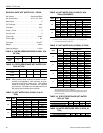
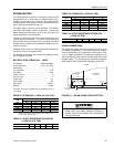
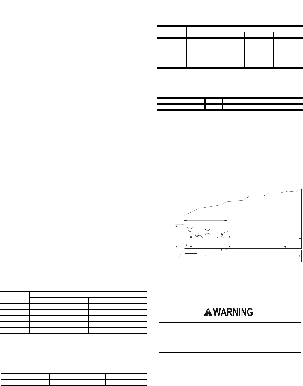
PIPING CONNECTIONS
The steam piping must enter the unit through the floor of the
heat section compartment. The access doors to the compart-
ment are gasketed to the compartment can be sealed. How-
ever, as added protection for condensate leakage into the
space, the piping access holes should be sealed with a heat
resistant mastic. The following figure illustrates the approxi-
mate location of the compartment and piping connections.
FIGURE 18 - STEAM PIPING CROSS SECTION
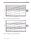
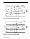
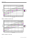
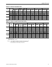
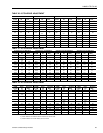
TABLE 20: STEAM COIL (1 ROW, 25 & 30 TON)
1
1.
Based on 60°F entering air temperature, 2.00” maximum air
pressure drop across the coil.
CFM
C
APACITY (MBH) AT STEAM PRESSURE (PSI)
261015
6000 194.1 207.9 219.8 232.6
8000 221.1 236.9 250.4 265.0
10000 243.2 260.5 275.4 291.4
12000 261.9 280.6 296.6 313.9
15000 285.6 306.0 323.5 342.4
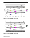
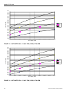
TABLE 21: STATIC RESISTANCE STEAM COIL
(1 ROW, 25 & 30 TON)
CFM 6000 8000 10000 12000 15000
A
IR PRESSURE DROP 0.11 0.18 0.26 0.36 0.54
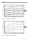
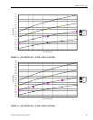
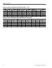
TABLE 22: STEAM COIL (1 ROW, 40 TON)
CFM
C
APACITY (MBH) AT STEAM PRESSURE (PSI)
2 6 10 15
8000 221.1 236.9 250.4 265.0
11000 252.9 271.0 286.4 303.1
14000 278.2 298.0 315.0 333.4
17000 299.4 320.7 339.0 358.8
20000 317.6 340.2 359.6 380.6
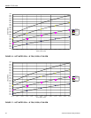
TABLE 23: STATIC RESISTANCE STEAM COIL
(1 ROW, 40 TON)
CFM 8000 11000 14000 17000 20000
A
IR PRESSURE DROP 0.18 0.31 0.48 0.67 0.88
DO NOT use tin based solder. Brazing with tin
based solder could cause equipment damage or
possible injury to OCCUPANTS of the structure that
is being conditioned.
S T E A M
C O I L
C O N D E N S I N G
S E C T I O N
O U T L E T ( 1 1 / 2 " )
C
L
2 .5 5 "
8 .3 8 "
2 6 "
1 5 .8 "
I N L E T ( 2 " )
8 "
9 "
H E A T S E C T I O N
C O M P A R T M E N T
8 8 . 7 5 "
T O P V I E W
O U T S I D E O F
B A S E R A IL